


m Drivers kqechanics
Page 21
If you've noticed an error in this article please click here to report it so we can fix it.
TEN SHILLINGS WEEKLY is paid for the best communication received, and one penny a line of ten words for anything else published, with an allowance for photographs.
Send us an account of any special incident of your work or experience. If suitable, we will edit your notes, supPly a sketch when required, and pay you for everything published. Mention your employer's name, in confidence, as evidence of good faith. Address to The Editor, THE COMMERCIAL MOTOR, Rosebery Avenue, London, E.C.
Light Up Your Lamps At 8.16 on Thursday ; 8.18 on Friday ; 8.20 on Saturdays 8.23 on Monday ; 8.25 on Tuesday ; 8.27 on Wednesday.
The Manufacture of Tubular Axles.
[1621] " H.M." (West Bromwich) writes :—" Owing to the increased demand for transport vehicles of all kinds, due to the requirements of the War Office, many manufacturers, not hitherto accustomed to this class of work have nevertheless found it advisable to apply their efforts to the manufacture of motorcar and lorry components.
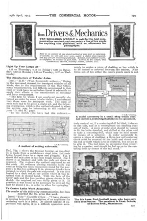
"The firm by whom I am employed recently obtained an order for some tubular axles ; I understand that these were for transport work. The ends of each axle had to be given a slight set, and the following description, which is the method adopted to effect the setting, may be interesting to the readers of your 'D. and M.' page.
"Iii the sketch [We have had this redrawn.—
ED.), Fig. 1 shows the tubular forging, as supplied. It is made from a, solid-drawn steel tube, the ends being forged down to a taper and plugged. Fig. 2 shows the axle after it has been rough turned. Fig. 3 shows it as finished and with the ends set down as required. Fig. 4 shows the method employed to set the ends. An ordinary planing machine table was used as being the most convenient stand for the purpose; to this two ordinary 31 in, plummer blocks were secured, in which the axle was supported. It was then heated to a dark red,at the points where it was required that it should bend. With the help of the screw jack and the two packing pieces shown in the sketch, the required set was easily given to it. In practice it was found to be necessary to over set the axle by about k in., in order to allow for springing."
To Centre Lathe Work Accurately.
The sender of the following communication has been awarded the 10s. prize this week.
[1622] "Toby" (Cardiff) writes :—" I have pleasure in sending herewith a description of an appliance for centering work in a lathe. As almost anyone of experience will agree, it is a difficult operation accu rately to centre a piece of shafting or bar which is to be turned or screwed between the centres. Nine times out of ten either the centre-punch mark is not
truly central, or, if a centering-drill bodied, it draws to one side, and as a consequence the shafting runs out of truth. A piece of mild steel should be turned to fit the lathe Mandrel, and drilled at the other end to take a centering-drill, which may be held secure by means of a setscrew. In order accurately to centre a piece of shafting, a three-jaw self-centering chuck must be screwed on the lathe and closed over the rod or shaft which is to be centered, but not so as to grip it. The rod must be prevented from revolving by a carrier, and should be fed up on to the centering drill by means of the tail stock."