


The Reclamation of Worn :ngine Valves by Stelliting
Page 30
Page 31
Page 32
If you've noticed an error in this article please click here to report it so we can fix it.
The Hard-facing of Engine Valves by the Welding in this Article Our Contributor Deals With
is Both an Economical and Practical Procedure. inique Necessary to Achieve Successful Results
ALL types of engine valve made of steel which are burnt in the seating, following the effects of leaded petrol, or which may have become excessively worn, can be reclaimed by hard facing with Deloro Stellite to give a life many times that of the original valve. This added life, brought about by hard facing, is of greater consequence when the valves are used with high-octane or leaded petrol.
Even with ordinary, petrol the hard facing of valves is, indeed, a profitable practice, as valves treated with Stellite last so much longer than do untreated valves. Further, the cost of depositing Stellite, and of the subsequent finishing operations, is much lower than the cost of new valves. • ' Reports from users show that a life of up to 50,000 miles is usually obtained with Stelilted valves even under present-day conditions as regards petrol and operation. '
To prepare a valve for Stelliting, the seating and all surrounding metal should be ground free from all carbon deposit and Scale, on a grinding wheel, and any burnt areas on the seating should also be ground out so that all cracks are removed.
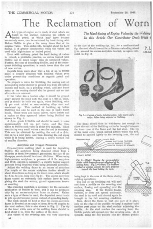
lithe valve has a feather edge it should be ground away around the head until the ,edge is 1 /32 in. thick, and it should be built out again, when Stelliting, with 3* per cent. nickel or wear-resisting alloy steel and machined up. This method of building up before Stelliting can also be used in the case of badly burnt heads. Some worn and burnt valves, valve inserts and a rocker as they appeared before being Stellited are shown in Fig. 1.
A -1-6--in. grade 6 Stellite rod should be used; it takes approximately 1/5 oz. per valve, and the time taken to Stelae each valve is about five minutes. When resurfacing very small valves a smaller rod is necessary. This can be obtained by melting the end of a 126-in, rod on to a cold plate, and then drawing the rod along while it is being melted, leaving a newly formed rod of smaller diameter.
Acetylene and Oxygen Pressures Oxy-acetylene welding plant is used for depositing Stellite, the acetylene being obtained either from a cylinder or from low-pressure generators; the size d1 the blowpipe nozzle should be about 100 litres. When using high-pressure acetylene, a pressure of 8 lb. acetylene and 10 lb. oxygen is necessary, a slightly higher oxygen pressure being required when using generator acetylene.
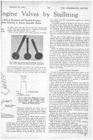
Adjust the welding flame to an excess of acetylene The length of the excess acetylene feather should be about three times as long as the inner cone, which should be 1-46 in, to in. long (see Fig 2). The excess acetylene flame causes an extremely thin surface layer to melt, giving the steel the watery, glazed appearance known as sweating.
This sweating condition is necessary for the successful application of Stellite to 'steel, and it can be produced only by an excess-acetylene flame as shown. Unless such a type of flame be used, the deposited metal tends to pile up and become porous instead of spreading freely.
The torch should be held so that the excess-acetylene flame is directed at an angle of from 30 to 60 degrees to the steel surface; this is also shown in Fig. 2. The tip of the inner white cone of the welding flame should be held about * in. from the surface of the steel.
The extent of the sweating area will vary according to the size of the welding tip, but, for a medium-sized tip, the steel should sweat for a distance extending about + in. around the excess-acetylene feather, as again indicated in Fig. 2.
The flame should then be withdrawn just enough to allow the end of the Stelliting rod to be brought between the inner cone of the flame and the hot steel. The tip• of the inner cone, which should almost touch the rod, should be applied lightly to the sweating area, the rod
being kept in the area of the flame during welding operations.
The end of the Stelliting rod will melt and form a puddle on the sweating steel surface, flowing and spreading over the sweating area. If the Stellite foams, bubbles; or does not spread uniformly, the steel is too cold and should again bebrought to the full sweating condition.
Now, direct the flame .so that one part of it plays only on the edge of the puddle—to keep it molten—and another part plays on the steel surfaCe adjoining the puddle. As the steel reaches the sweating heat, the Stellite puddle will spread over the sweating area. As it spread% bring the rod quickly into the molten puddle
of metal, and with the end of the rod touching the, puddle, melt more Stellite into it. Continue these steps steadily until the desired area is coated. . With a little practice the correct amount of Stellite can be added to make the deposit the desired thickness, and it is sometimes better to cover the area in one operation, or with one pass of the torch, than to go back over the whole job and add another layer of Stellite.
During the operation, the flame can be repeatedly moved back to melt just a thin surface layer of the deposited Stellite so as to smooth out high spots just behind the molten puddle.
This should be done quickly without allowing the front edge of the puddle to solidify, or interrupting the steady forward progress of the work. If desired, a second pass can be made with the flame to insure a smooth surface that will require a minimum amount of grinding. If a second pass be made, the Stellite should not be melted down to the base metal—only the surface layer of the deposit should be melted. Melting any deeper causes dilutionof the Stellite by iron from the base metal, and this considerably impairs the quality of the deposit.
The puddle should be flowed in the direction desired by means of the flame, not by stirring with the rod. Usually, the work progresses toward the hand holding the Stelliting rod, but on steel which scales badly, or on very thin sections, the backhand method, shown in Fig. 3, is sometimes used. Following this technique, the work progresses toward the hand holding the welding torch.
If any dirt or scale appears on the steel, or in the puddle, float it to the surface with the flame. If it will not float, dislodge it with the rod. In extreme cases it may be necessary to use a good cast-iron welding flux. Where finishing operations, such as grinding, are necessary, the deposit should be slightly reinforced•to allow for this.
When the Stellite deposit has been built up to the desired size and thickness, remove the flame slowly from the puddle to prevent the formation of shrinkage cracks or small holes. To do this, withdraw the flame as indicated by the arrows in Fig. 4. If cracks or holes be present, remelt the deposit in the immediate vicinity of the faulty places, flick any articles of scale or oxide from the pool with the rod, and add a little more Stellite. If the holes still appear, it may be necessary to grind off the Stelae deposit down to the steel at that spot, and then to warm the area gradually with the torch and deposit new Stellite.
Careful Cooling Necessary So soon a the deposit has cooled down below a red heat, it is necessary to place the entire part in a box of powdered mica, lime, ashes or other similar insulating material so that it will cool sloWly. In many cases, slow cooling is absolutely essential to produce a deposit free from cracks and internal stresses.
Parts which show a strong tendency to crack are usually placed in a heat-treating furnace while still hot from welding, brought slowly to a low red-heat—about 620 degrees C.—and then allowed to cool, slowly in the furnace with the door closed and the heat turned off. Never cool a part by dipping it in water.
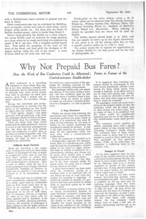
To help the operator to Stellite around a valve seat, the valve should be stood on a piece of copper plate. The copper and the valve can then be placed on a disc such as a gear wheel, which can be pivoted around a ;vertical axis during Stelliting. This helps to obtain an even and continuous deposit. When large numbers of valves are to be hard faced, or the operation is a regular or continuous one, it is an advantage to construct a ' proper jig, which is mechanically rotated at the rate of one revolution in two minutes, movement being controlled by the foot of the operator. Fig. 5 gives a rough impression of such a rig up.
Should the valve not be the required thickness after welding operations are completed, the whole procedure of building up will have to be repeated, but after practice it should be possible to obtain the required depth of deposit in one run around the valve head.
Fig. 6 illustrates successive stages in the Stelliting and grinding of a worn and cracked valve.
Stellite cannot satisfactorily be applied direct on to the valve seatings in cast-iron cylinder blocks. Stellitefaced valves work satisfactorily in conjunction with a cast-iron seating, or inserted seatings of any type. Best results of all are obtained when using a Stellited valve
with a Stellited-steel insert screwed or pressed into the bead or block.
Other components also can be reclaimed by Stelliting, such as tappets, rockers and ends of valve stems, clutch fingers, pump shafts, etc. For these jobs use Grade 12 Stellite (marked green), which is harder than Grade 6.
Before finish-grinding the Stellite on a valve refacer, the excess Stellite must be removed by rough grinding on a large wheel or by rough machining at a commencing speed of 30 ft. per min. with a tungsten-carbide-tipped tool. First grind the periphery of the head on the front of the wheel and then grind the 45-degree or 30degree seating, using the side of the wheel. A small Y-block fitted on the work rest, will help. Finish-grind on the valve ref acer, using a 60 M wheel, which can be obtained from The Norton Grinding Wheel Co., Welwyn Garden City, Welwyn, Hats, The Universal Grinding Wheel Co., Stafford, or Mitchell's Emery Wheel Co., Manchester. When ordering, it should be specified that the wheel will be used for Stelae.
The Stellite deposit should finish -fig in. thick, and this can usually be taken up by the tappet adjustment. If not, grind Tigin. off the seating either flat, or with a smooth concave radius up to 1/32 in. deep.
The author would like to express his appreciation to the Deloro Stellite Co. for help given and for the loaie of photographs, etc.