


A New Type of Refuse.collection Body
Page 56
If you've noticed an error in this article please click here to report it so we can fix it.
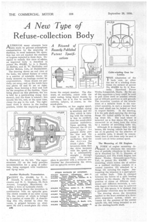
ALTHOUGH many attempts have been made to prevent atmospheric contamination by the emptying of dustbins, in most instances the operation has not yet reached the standard of hygiene expected in these days. Designed to remedy this state of affairs, an improved body is described in patent No. 414,691, by A. J. Burrell, of Halifax, and H. W. Hattersley and Karrier Motors, Ltd., of Huddersfield.
The drawing thews an end view of the body, the salient feature of which is a number of rotatable drums (4) freely mounted on bearings carried by cross-members. These drums are partially cut away, and on the inside have two plates (2 and 3) set at rightangles, these forming a floor and wall for the reception of the dustbin. Upon being placed on this platform, the bin is held by a quick-acting clamp (not shown), and the drum is rotated; this inverts the bin, and, at the same time, closes the gap in the wall. The righthand drum is shown in the loading position, whilst the emptying position Another Hydraulic Transmission.
PATENT No. 414,898, by T. G. Hassan, 9, Albert Square, Manchester, and R. G. Stephens, 18, Park Avenue, Longsight, Manchester, describes a form of hydraulic clutch.
The drawing shows the invention in combination with an epicyclic gear. The clutch consists of an outer casing (1), the interior of which is bridged by a number of vanes (2). A close-fitting disc (3), slotted to clear the vanes, is gripped between an abutment (4) and a swash-plate (5) which B46 forms the output member. The disc must, of necessity, rotate with the outer casing, being keyed thereto by the vanes, but it is free to oscillate endwise, subject, of course, to the swash-plate.
In operation, at low engine speed, the oil-filled casing is revolved, and the disc, which is turning with the casing, is free to oscillate, thus the swath-plate remains stationary, Upon speeding up, however, the oil can no longer be pumped freely past the disc and the result is to check oscillation; thus the disc drives the swath plate. The inventors claim that the drive increases with the speed, up to a substantially straight through ratio. The swathplate is provided with a retractor mechanism for discontinuing the drive, and an epicyclic reverse gear.
T1-TB adaptation -of the back axle to allow the use of a winding drum forms the subject of patent No. 414,964 by D. S. Kennedy, Harewood Forest Works, Longparish, Hants. By the use of this apparatus a lorry could be used to pull either itself or another vehicle out of difficult positions in soft ground. The invention consists of the attach.ment of a suitable drum to the rearwheel assembly, in such a manner that the road wheel can be locked or freed
in respect thereto. In the drawing, 4 is the axle shaft carrying the driving flange (5) bolted solidly to the winding drum (2). The road wheel is mounted on a free sleeve (3), and is connected to or freed, from the drive by a number of swivelling bolts (1).
Although it is .claimed that, by this means, the towing vehicle has the full use of its gearbox for the selection of a suitable ratio, it should be remembered that if one drum only be used it would turn at twice normal speed.
The Mounting of Oil Engines.
A FORM of engine mounting designed to eliminate the transmission of periodic vibraticns to the chassis is described by. W. L. Paynter, of Gateshead, and The Forth Engine and Motor Works, Newcastle-upon-Tyne,
Ltd., in patent No. 414,763. This mounting, which makes use of rubber as a resilient medium, consists of a central trunnion (3) attached to a flange (2) carrying the engine. Surrounding the trunnion is a part-spherical rubber bush. This is clamped between the halves of a split bearing attached to the chassis. ,By the interposition of shims of different thicknesses and different materials, a variable degree of friction may be achieved and, by this means, it is claimed that a particular vibration may be checked.
The drawing shows the invention applied to the front member of a threepoint suspension system, which accounts for the presence of the central spindle (4), this being intended to act as the starting-handle shaft.