


A CUFF-VALVE ENGINE.
Page 62
If you've noticed an error in this article please click here to report it so we can fix it.
A Resume of Recently Published Patent Specifications.
ANEW form of cuff-valve engine is described in specification No. 256,470, of H. J. Howard, a name already associated with an engine of this class that attracted considerable attention at Olympia some years ago.
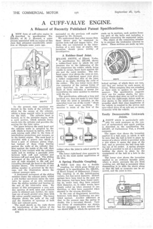
In the present case openings are formed in the walls of the cylinder to allow for the escape of the exhaust, whilst a large central valve is provided for the inlet. The cylinder head is formed, as in the previous engine, with a sunk portion, which extends downwards into the cylinder and provides the seating for the inlet valve.
The space between the sunk head and the cylinder walls is occupied by the cuff, which is formed in halves, with its ends joining each other in the form of interlocking projections and recesses, as in the former engine. The sunk head is provided with a groove into which is fitted a pair of ordinary piston rings, but instead of these rings bearing against the walls of the cylinder they bear against the inside of the cuff, thus forcing it into contact with the cytinder walls and so making a gas-tight joint between both cuff and cylinder and between cuff and sunk head. The sliding movement of the cuff is effected by a pair of rods attached to the cuff and extending through the head to the sliding member shown. The movement of this sliding member is governed by the face cam, and the illustration shows the exhaust passages open.
A downward movement of the sliding member closes the exhaust ports, whilst a still further movement opens the inlet valve by means of an arm extending from the sliding member and bearing on the end of the inlet-valve stem. By means of this arrangement a very sudden opening of both islet and exhaust ports is obtained and, further, the openings are of much greater area than with the valves usually employed. The lower diagram shows the path of the cuff and the duration of openings of both inlet and exhaust ports.
The small sketch on the right shows the interlocking of the halves of the cuff, which we are informed proved very B44 successful on the previous cuff engine designed by Mr. Howard.
We understand that other means than those shown may be employed to operate both cuff and tappet valve. For those who are interested in the introduction of a new type of engine, this invention should prove worthy of investigation.
A Rubber-lined Joint.
F,RANK SMITH, of Elland, Yorks, in specification No. 257,009, shows a rubber-lined joint in which the end pressure due to 'the tightening of the nut compresses the rubber, which, being unable to escape, bears hard against the pin and the outer member. The lefthand upper view shows the joint at rest, whilst the right-hand upper view gives a rather exaggerated idea of the joint when at an angle, showing the yield of the rubber. The two lower views show two examples of the various forms of joint described in the specification. Each of these indicates a means for centralizing the outer member in relation with the pin.
The specification, although a long and involved one, does not make it very clear for what the joint is intended, as the somewhat loose use of the words "shock absorber" may mean anything. No mention is made of the flow of the rubber when the joint is asked partly to revolve.
The lower right-band view appears to us to be the most useful application of the idea.
A Spring Flexible Coupling.
AVERY bold idea for a flexible coupling, for which great things are claimed, is in specification No. 249,831, of Henri reign& of Billaneourt, France. The coupling is of the helical-spring variety, but has novel features. Helical springs have been tried in the past for this purpose, but have been found wanting as, under load, they have reduced their diameter, or, in other words, have simply coiled up when stressed in one direction, or they have expanded when stressed in the reverse direction.
In the case of thetpresent invention, however, both these tendencies are provided against. Another difference is that in the present case the spring is double, like a two-start thread. Various forms of construction are shown, butfor clearness we have selected the one showiTIM in which the springs are made up in sections, each section forming part of the helix and including a member connecting the segmental parts.
The object of the connecting member is to prevent the tendencies referred to above. These sections are made up into helical springs, of which there are two and they are united by such means as rivets. When complete they are attached, at their ends to spiders in the usual manner. The specification suggests their use for cardan shafts, for driving of wheels that steer as well as drive, and even for right-angle drives such as that shown in the small, view, where, a propeller shaft that runs lengthwise of the vehicle is coupled to the pinion and spur-wheel drive of an axle set, as usual, crosswise with the vehicle.
Easily Demountable Linkwork Joints.
A JOINT which is particularly suit
able for such purposes as the control of carburetters and spark position is described in the specification No. 237,887, of Carburateur Viel, a French company.
The upper view shows the invention applied to a ball joint, in which it will be seen that the ball is held in place by means of a sleeve which is provided with a slot where it spans the stem of the ball, and so prevents the ball from falling out of its socket. A. spring plunger or ball is provided to act as a means for holding the sleeve in place by the engagement of the ball in a hole in the sleeve.
The lower view shows the invention applied to an ordinary knuckle joint, where a sleeve prevents the pin from working out. All that is necessary vithen dismantling is to slide the sleeve along so that the ball or cross-pin can be removed, and the joint is free.