


Cushioned Leaf Suspension
Page 80
If you've noticed an error in this article please click here to report it so we can fix it.
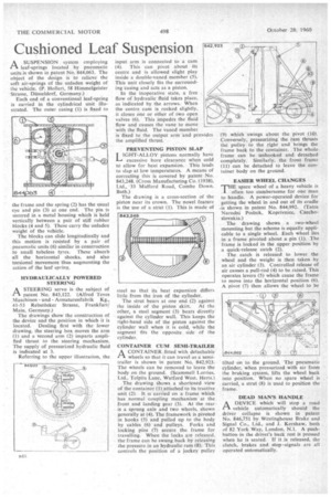
A SUSPENSION system employing 1-1 leaf-springs located by pneumatic units is shown in patent No 844,063. The object of the design is to relieve the soft air-springs of the unladen weight of the vehicle. (P. Hollert, 58 Himmelgeister Strasse, thisseldorf, Germany.)
Each end of a conventional leaf-spring s carried in the cylindrical unit illustrated. The outer casing (1) is fixed to the frame and the spring (2) has the usua eye and pin (3) at one end. The pin is secured in a metal housing which is held vertically between a pair of stiff rubber blocks (4 and 5). These carry the unladen weight of the vehicle.
The blocks can slide longitudinally and this motion is resisted by a pair of pneumatic units (6) similar in construction to small tubeless tyres. These absorb all the horizontal shocks. and also torsional movement thus augmenting the action of the leaf spring.
HYDRAULICALLY POWERED STEERING
ASTEERING servo is the subject of -patent No. 843,122. (Alfred Teves Maschinen und Armaturenfabrik Kg., 41-53 Rebstocker Strasse, Frankfurt/ Main, Germany.)
The drawings show the construction of the device and the position in which it is located. Dealing first with the lower drawing, the steering box moves the arm (1) and a second arm (2) imparts amplified thrust to the steering mechanism. The supply of pressurized hydraulic fluid is indicated at 3.
Referring to the upper illustration, the input arm is connected to a cam (4). This can pivot about its centre and is allowed slight play inside a double-vaned member (5). This unit closely fits the surrounding easing and acts as a piston.
In the inoperative state, a free flow of hydraulic fluid takes place, as indicated by the arrows. When the centre cam is rocked slightly, it closes one or other of two open valves (6). This impedes the fluid flow and causes the vane to move with the fluid. The vaned member is fixed to the output arm and provides the amplified thrust.
PREVENTING PISTON SLAP 101-IT-ALLOY pistons normally have excessive bore clearance when cold to allow for heat expansion. This leads to slap at low temperatures. A means of correcting this is covered by patent No. 843,248. (Cross Manufacturing Co. (1938), Ltd., -33 Midford Road, Combe Down, Bath.)
The drawing is a cross-section of the piston near its crown. The novel feature is the use of a strut (1). This is made of steel so that its heat expansion differs little from the iron of the cylinder.
The strut bears at one end (2) against
the inside of the piston skirt. At the other, a steel segment (3) bears directly against the cylinder wall. This keeps the right-hand side of the piston against the cylinder wall when it is cold, while the segment -fits the opposite side of the cylinder.
CONTAINER CUM SEMI-TRAILER
ACONTAINER. fitted with detachable wheels so that it can travel as a semitrailer is shown in patent No. 842,923. The wheels can be removed to leave the body on the ground_ (Scammell Lorries, Ltd., Tolpits Lane, Watford West, Herts.) The drawing shows. a shortened view of the container (1). attached to its tractive unit (2). It is carried on a frame which has normal coupling mechanism at the front and landing gear (3). At the rear is a sprung axle and two wheels, shown generally at (4). The framework is pivoted in hooks (5) and pulled up to the body by cables (6) and pulleys. Forks and locking pins (7) secure the. frame for travelling. When the locks are released, the frame can be swung back by releasing the pressure in an hydraulic ram (8). This controls the position of a jockey pulley
(9) which swings about the pivot (10). Conversely, pressurizing the ram thrusts the pulley to the right and brings the frame back to the Container. The whole frame can be unhooked and detached completely. Similarly, the front frame (11) can be detached to leave the container body on the ground.
EASIER WHEEL CHANGES "THE spare wheel of a heavy vehicle is often too cumbersome for one man to handle. A power-operated device for getting the wheel in and out of its cradle .is shown in patent No. 844,992. (Tatra Narodni Podnik, Koprivnice, Czechoslovakia.) The drawing shows a two-wheel mounting but the scheme is equally applicable to a single wheel. Each wheel lies in a frame pivoted about a pin (1). The frame is locked in the upper position by a quick-release catch (2).
The catch is released to lower the wheel and the weight is then taken by an air cylinder (3). Controlled release of air causes a pull-rod (4) to be raised. This operates levers (5) which cause the frame to move into the horizontal position (6). A pivot (7) then allows the wheel to be tilted on to the ground. The pneumatic cylinder, when pressurized with air from the braking system, lifts the wheel back into position. When no spare wheel is carried, a strut (8) is used to position the frame.
DEAD MAN'S HANDLE ADEVICE which will stop a road vehicle automatically should the driver collapse is shown in patent No. 846,751 by Westinghouse Brake and Signal Co., Ltd., and J. Kershaw, both of 82 York Way, London, N.1. A pushbutton in the driver's back rest is pressed when he is seated. If it is released, the clutch, brakes and stop -signals are all operated automatically.