


MAKING BEST USE OF THE FORD.
Page 32
If you've noticed an error in this article please click here to report it so we can fix it.
Valuable Advice on Every Phase of Ford Transport, Which Will Appeal to the Owner, Driver and Repairer.
IN THIS series of hints concerning the Ford light chassis and ton truck wherever they are employed for commercial purposes, we endeavour to deal with the subject from every view-point., so that the advice given will appeal to the owner, driver, maintenance engineer or mechanic. Valuable sources of information are being tapped for this purpose.
We shall welcome for inclusion among the hints those which have proved of value to individual users, and will make suitable remuneration for any such information which we publish. What we desire are the results of actual practice. Readers are recommended to obtain the original " Book of the Ford," which constitutes a complete manual dealing with the Ford car, the van and the truck. 2s. 9d. post free from the offices of this journal.
251.—A Mysterious Ignition Trouble and its Solution.
An ignition trouble, the cause of which may remain a mystery for some time, can frequently be traced to the contact plate which runs along the bottom of the coil box. The fingers in this sometimes fracture, become detached from the metal strip and fail to make contact with their respective coils, besides which, the loose portion or portions wilI wander about the bottom of the box and cause missing, as shorts occur between the contact plate and the coil box, and from there to earth via the radiator tie rod, which lies immediately behind the box.
In the event of this happening on the road, the current may be taken from the next coil by joining with wire the contact buttons on the bottom of same, the edges of which can be easily lifted by the aid of the blade of a penknife, and then pressed down again after the insertion of the wire.
A soldered connection will effect a permanent repair until the coil box be dismantled, providing, of course, that a pair of wired-up coils be always used
252.—Making the Ford Petrol Tap More Accessible.
The petrol tap on the Ford can he made much more accessible, or, perhaps it would be better to say, can be operated in a more convenient manner, by using a suitable connection between the handle of the tap and the outside of the chassis frame.
To achieve this result, take a piece of g-in. round steel, 11 ins, long, and drill in this a 17ff-in. hole to a depth of in. Drill and tap the other end 16,-, in. and slot out the larger hole at one side to fit over the petrol tap. Now cut a piece of 16,7-in. rod long enough to extend from the tap end of the device to the outside of the chassis frame, leaving sufficient to bend out at right angles to form a handle.
Between the inner side of the channel and a pinheld washer or collar on the rod fit a light sprang, to keep the rod up to its work, and the rod should be screwed tightly and pinned into the end operating the tap, making certain that the handle is down when the tap is on. A small hole must be drilled in the. chassis frame, the whole arrangement being as illustrated.
253.—An Easily Made Testing Rig for the Coils.
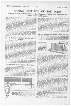
A coil tester of the type illustrated was made some time ago by one of our readers from information contained in an article in The Motor, and it was found to give very satisfactory results in practice. The
whole apparatus, excluding the accumulator, can be made from scrap, etc., at the cost of about is.
Referring to the letters on the sketch, A is the coil in position to be tested, B is the baseboard, which should be about 10 ins. by 6 ins, by in., and to this is nailed a strip of wood, 4 ins. by I in. by
in., against which the coil box must butt.
Two strips of spring brass (C and D) are screwed to the base board. Each should be lj in. wide and made from 16 s.w.g. material bent to the shape shown, so that they will admit the coil-box for test. The free end of C presses firmly on the contact E, and the free end of D does likewise on contact F. Immediately over contact 0 and passing through C is a 4 B.A. brass screw (H), a piece of brass being soldered to C to accommodate this screw, the top of which should be insulated to permit adjustment while the current is on.
A six-volt accumulator is required for testing, the wires being connected to the switch (L), and from , this to the two strips.
To test a coil, the current is switched on, and if the coil is in order a loud buzzing will be heard and a stream of sparks will pass from the point of screw (H) to the contact (0), providing that this has been adjusted so that the gap is not too great. If the coil is defective, the buzzing will be heard, hut no stream of sparks will be seen. If neither buzzing be heard nor sparks seen, truing, cleaning and adjusting the trembler (K) may put matters right, but if still no result be obtainable the coil is worn out and of no further use ; the cost of replacement is comparatively small, consequently, rewinding would not pay. A good coil may give sparks up to I in. long between H and G, and they should certainly not be less than 3in. long.
Never let the coil buzz for long if sparks do not pass, otherwise further damage may be done to the interior.