


Constant-height Suspension
Page 80
If you've noticed an error in this article please click here to report it so we can fix it.
A SUSPENSION system which is EA adjusted automatically to maintain a constant chassis height is shpwn in patent No. 790,104, The scheme employs leaf springs so that it can be applied to a vehicle with the minimum of alteration. (Ford Motor Co., Ltd., 88 Regent Street, London, W.I.), The spring. is .attached conventionally at the rear by a shackle (1). At the front, however, the top leaf is pivoted and has
extending from it a short crank (2). This if turned clockwise, applies torque to the spring and so tends lb raise the vehicle frame. . .
The crank is operated by a hydraulic . cylinder (3) which acts through a heavy tension spring (4). The control valve (5) is not shown in detail, but it is fitted with _ sensing device which continually measures the axle-to-frame height and applies the appropriate correcting force.
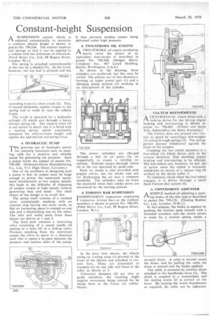
A HYDRAULIC PUMP T"growing use of hydraulic power for assisting functions such as steering, calls for a positive and reliable pump for generating the pressure. Such a pump forms the subject of patent No. 790,388. (Hobourn-Eaton Manufacturing Co., Ltd., 9-11 High Street, Coventry.)
One of the problems in designing such a pump is that its output must be large enough to power the associated equipment satisfactorily at low engine speeds; this leads to the difficulty of disposing of surplus output at high speeds without generating heat and noise. The chief object of the design is to avoid this.
The pump itself consists of a toothed rotor, eccentrically meshing with an internal ring having one more tooth, so that an increasing space is created on one side and a diminishing one on the other. The inlet and outlet ports from these spaces are shown at I and 2.
The fluid path contains a restricting valve consisting of a coned needle (3) seating in a bore (4) in a sliding valve. Pressure resulting from the restriction causes the valve to move in a direction such that it opens a by-pass between the pressure and suction sides of the pump It thus prevents surplus output being delivered under high pressure.
A TWO-STROKE OIL ENGINE ATWO-STROKE oil engine producing nearly twice the power of an equivalent four-stroke is described in patent No. 790,508. (Hedges Motor Company Inc., 407 Lloyd Building, Seattle, Washington, U.S.A.) As shown in the drawing, three cylinders are preferred, but this may be varied. The pistons are of two diameters, forming. an upper power 'part(1) and a charging pump portion (2) working in an enlargement of the cylinder.
The power cylinders are charged through a belt of air ports (3), set tangentially to create a rotating air column. Exhaust occurs through valves (4) at the top operated by push-rods. Each air pump is also provided with poppet valves, one for intake and one for discharging the air into a common manifold. The cylinders take air from the manifold when their intake ports are uncovered by the moving pistons.
A TORSION BAR SUSPENSION INDEPENDENT suspension employing I transverse torsion bars as the resilient members is shown in patent No. 790,392. (Fettd Motor Co., Ltd., 88 Regent Street, London, W.1.) In the plan view shown, the wheels swing on trailing arms (1)pivoted at the front of the chassis and attached to torsion bars. These are journalled in brackets (2) on one side and fixed at the other as shown at 3.
Telescopic dampers (4) act also as guide members, the resulting slight angular movement being catered for by fixing them to the frame via rubber blocks.
CLUTCH REFINEMENTS ACENTRIFUGAL clutch fitted with a locking device for use during engine braking and tow-Starting is shown in patent No. 790.465. (Fichte! and .Sachs A.G., Schweinfurt am Main, Germany.) The friction discs are pressed into contact at speed by centrifugal bob-weights (1) acting through springs (2). The springs permit manual withdrawal againstthe force of the weights.
Coupling the two clutch members is a free-wheel (3) which drives only in the• reVerse direction, thus enabling engine braking and tow-starting to be effected. The free-wheel can, however, be put OM of action when the clutch is manually withdrawn by means of a release ring (4) worked by the thrust collar 5.
To eliminate shock when the free-wheel engages, it is driven through a small fixed friction-disc system (6).
A CONVENIENT ADJUSTER
ASIMPLE method of adjusting a parking brake of the disc type is described in patent No. 790,126. (Dunlop Rubber Co., Ltd., London, N.W.1.)
In this scheme, the brake is applied by pushing the friction pads inward with a threaded actuator, and the return stroke is made by a torsion spring inside a co-axial drum. A cable is wound round the drum, and by pulling the cable the drum is rotated and the brake applied.
The cable is actuated,by another drum attached to the handbrake lever (1). The drum is coupled to a wormwheel, and the mating worm (2) is carried on the lever. By turning the worm thumbscrew as required, the cable can be tightened.