


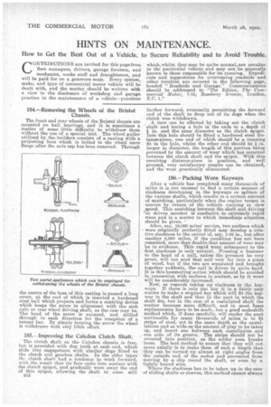
184.—Removing the Wheels of the Bristol Chassis.
Page 30
Page 31
If you've noticed an error in this article please click here to report it so we can fix it.
The front and rear wheels of the Bristol chassis are mounted on ball bearings, and it is sometimes a matter of some little difficulty to withdraw them without the use of a special tool. The wheel puller utilized by the builders consists of a casting with a projecting boss which is bolted to the wheel nave flange after the axle cap has been removed. Through the centre of the boss of this casting is passed a long screw, at the end of which is inserted a hardened steel ball which projects and forms a centring device which keeps the screw in alignment with the stub axle or rear wheel driving shaft, as the case may be. The head of the screw is squared, and drilled through in each direction for the reception of a tommy bar. By simply turning the screw the wheel is withdrawn with very little effort.
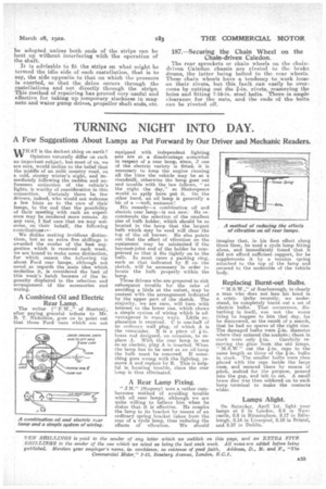
185.—Improving the Caledon Clutch Shaft.
The clutch shaft on the Caledon chassis is free, but is provided with dog teeth at each end, which slide into engagement with similar dogs fitted to the clutch and gearbox shafts. In the older types the clutch shaft had a tendency to work forward, with the result that its face c,anie into contact with the clutch spigot, and gradually wore away the end of this spigot-, allowing the shaft to come still B12 farther forward, eventually, permitting the forward end of the shaft to drop out of its dogs when the clutch was withdrawn.
A cure can be effected by taking out the clutch shaft and boring a hole in the ends to a depth of
in. and the same diameter as the clutch spigot. Into this hole should be fitted a hardened steel distanceepiece, one end of which should be a running fit in the hole, whilst the other end should be i in_ larger in diameter, the length of this portion being governed by the amount of wear which has occurred between the clutch shaft and the epigot. With this revolving distance-piece in position' and well greased, very satisfactory results can be obtained, and the wear practically eliminated.
186.—Packing Worn Keyways.
After a vehicle has completed many thousands of miles it is not unusual to find a certain amount of slackness developing in the keyways or splines of the various shafts, which results in a certain amount of snatching, particularly when the engine torque is uneven by reason of the vehicle running at slow speed. This snatching between the shaft and driving or driven member is conducive to extremely rapid wear and is a matter to which immediate attention should be given, After, say, 10,000 miles' service, two surfaces which were originally perfectly fitted may develop a relative slackness to the extent of, say, 1-32 in., but after another 2,000 miles, if the condition has not been remedied, more than double that amount of wear may be in evidence. This rapid wear subsequent to the first slackness is only natural. Pressing a hammer to the head of a nail, unless the pressure be very great, will not send that nail very far into a piece of wood, but if the two are separated and brought together suddenly, the nail is driven in quite hard. It is this hammering action which should be avoided in connectien with surfaces in contact, as by it wear will be considerably increased. Now, as regards taking up slackness in the keyways. If there is only one key it is a fairly easy matter to make a stepped key which will fit the keyway in the shaft and that in the part in which the shaft fits, but in the case of -a castellated shaft the matter becomes more difficult, and in most eases replacements have to be made, but a good makeshift method which, if done carefully, will render the part serviceable for many thousands of miles is to fit strips of steel, out to the same depth as the castella,tions and as wide as the amount of play to be taken up, and insert one between each castellation and one side of its groove. The strips should not be sweated into position, as the solder soon breaks loose. The best method to ensure that they will not move axially is to make them of such a length that ' they can be turned up almost at right angles from the outside end of the socket and prevented from moving by a clip round the shaft, or even by a tightly bound wire.
Where the slackness has to be taken up in the case of sliding shafts or sleeves, this method cannot always be adopted unless both ends of the strips can be bent up without interfering with the operation of the shaft.
It is advisable to fit the strips on what might be termed the idle side. of each castellation, that is to say, the side opposite to that on which the pressure Is exerted, so that the drive occurs through the castellations and not directly through the strips. This method of repairing has provedvery useful and effective for taking up temporary slackness in magneto and water purap drives, propeller shaft ends, etc.
187.—Securing the Chain Wheel on the Chain-driven Caledon.
The rear sprockets or chain wheels on the chaindriven Caledon chassis are riveted to the brake chums, the latter being bolted to the rear wheels. These chain wheels have a tendency to work loose on their rivets, but this fault can easily be overcome by cutting out the s-in. rivets, reamering the holes and fitting 7-16-in, steel bolts. There is ample clearance for the nuts, and the ends of the bolts can be riveted O.