


HINTS ON MAINTENANCE.
Page 60
If you've noticed an error in this article please click here to report it so we can fix it.
Another Way of Compressing the Foden Front Spring. A Magneto Strap for the J-type Thornycroft. Attending to the Emergency Lubricators on Steam Wagons.
Removing and Replacing Foden Front Springs.
OE of our readers has observed with interest in 'L./recent issues of this paper two articles which have dealt with the Foden front spring, but he employs a method which he considers better than either of those given.
• To remove the spring, jack up the front axle at one side, reniove one wheel, and make up the space between
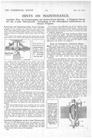
the ground and the bottom of the swivel jaw with wood. Lower the jack, knock out the too pin of the spring, but leave undisturbed the pin through the axle and apply a clamp, constructed as shown in the diagram. The spring will then be released as the nuts are tightened, or, if the spring has broken leaves, it can be knocked out with a fairly heavy hammer.
To fit the new spring, put the spring into position between the jaw so far as it will go, but in this instance fix the clamp in the reverse direction; tighten the nuts, and the spring will then compress until the block on it clears the top of the swivel jaw. The -spring to clear the slipper and screw up the nuts are tightened, and finally it butts against the off-side spring slipper. Drive a wedge, or chisel, below the spring to clear the slipper, and screw up the nuts until the spring is central. Now take a piece of round steel, tapered at one end and of the same diameter as the top pin, and drive this through the hole for the top pin. Follow it up with the proper pin, split-pin this and replace the wheel.
The method may seem complicated, but it has been used with success on many occasions, and the whole job can be done in less than an hour. With both the previous methods the front axle had to be removed, and this naturally takes more time. As an alternative to the employment of a tapered pin, a second clamp can be employed at the same time, but operating in the opposite direction, as shown by the dotted line in the sketch.
With this method there is no tendency for the clamp to slip, as the pull merely farces it against the end of a leaf.
The material required consists of two pieces of Fin. steel bar screwed Fin. Whit., four nuts to suit and two pieces of iron in. by in. and with a length of 10i ins. Horse-shoeing iron is suitable. Drill a Fin. clearance hole at the ends of these. The wedge, or chisel, should be tapered to a maximum thickness of *in.
Securing thq Magneto on the 3-type Thornycroft. ON the J-tylg Thornycroft lorry the magneto is held
down by two Fin. studs which screw into the face of the instrument. Sometimes, however, the internal threads strip and the magneto cannot then be held unless some other means be employed.
B42 To overcome this difficulty, one of our readers made use of a strap constructed of hard brass. He used two. strips of brass, each about 2 ins, wide and 9 ins, long,' these dimensions varying according to the size and' type of magneto employed.
At the bottom of each strip should be drilled -three
boles to take-146-in. studs. Tap out suitable holes in the magneto standard and shape the straps around the magneto, leaving about j in_ vertically above the top of each to take a i-in, bolt and nut, which, when tightened, will secure the magneto, Keep the Emergency Lubricator Ready.
MOST makes of steam wagon are fitted with dis placement lubricators for emergency use when the oil pump fails, and as this type of lubricator is seldom brought into action it is often neglected, with the result that when it is necessary to employ it it will not always work satisfactorily. The following description of the working of a displacement lubricator will enable drivers to obtain the best service from this important accessory. Reterring to the diagram, when the valve (A) en the top of the lubricator is opened, steam is brought into the lubricator in the form of a fine jet. This steam condenses and forms water. The water, having a greater density than the oil, sinks to the bottom and displaces the oil, which gradually reaches the top of the feed pipe (B) and overflows into the steam chest.
There are certain items which should, therefore, receive special attention. See that the drain tap (C) is opened before filling the lubricator. This will drain oft through the drain pipe (D) any water which may be contained in the lubricator. Then close the drain tap and pour in oil through the inlet (E) until it is nearly full. Never -fill to the top, because allowance has to be made for expansion.
Regulate the supply of oil to the cylinders by means of the regulator valve (A) ; usually about one-eighth of a turn is sufficient, for if more steam be admitted the oil may feed too rapidly and, consequently, run to waste. Water which has been mixed with oil often looks like oil in the lubricator, so it is hf the utmost importance to make certain that the lubricator is actually filled with oil and not merely with oily water.
Always keep the lubricator replenished with oil so that it can be brought into use immediately in case a oil-pump failure, for if a wagon be allowed to run— even for a few minutes—without lubricant, the slide valves and cylinder walls will be scored.