


SIMPLE MECHANICS
Page 42
If you've noticed an error in this article please click here to report it so we can fix it.
Propellor shafts and
universal joints Precepti
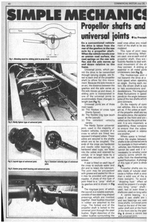
On a conventional vehicle the drive is taken from the rear of the gearbox to the rear axle by a propeller shaft. When the vehicle travels over an uneven road surface, the road springs on the rear axle flex and the axle moves up and down relative to the frame.
Universal joints, which permit the drive to be transmitted through varying angles, are fitted to each end of the propeller shaft to allow for this movement. Because the axle moves in an arc, the distance between the gearbox and the axle varies as the axle moves up and down. A sliding joint is incorporated in one of the universal joints to accommodate these changes in length (see Fig 1).
Universal joints are of three main types.
(a) The Hookes or cross type (Hardy Spicer); (b) The flexible ring type (such as the Layrub); (c) The constant velocity variety.
The Hardy Spicer universal joint, used in the majority of modern vehicles, consists of a cross to which are fitted two opposed U-shaped yokes. These yokes are secured to the shafts which are to be coupled. The ends of the cross are hardened and needle roller bearings, in hardened steel cups, are fitted into the yokes and retained by circlips, or in larger sizes by a steel plate secured by two set screws.
A seal is fitted on each leg of the cross to exclude water and dirt and to retain the lubricant. The joint may be pre-packed with grease and sealed for life or it may be provided with grease nipples. A photo of this type of joint fitted to a -propshaft at its gearbox end is shown in Fig 2.
The ring-type joint, of which the Layrub is a notable example, consists of two steel ring-shaped pressings which are rivetted together. Steel bushes mounted in rubber are attached to the rings. The forked end of the propeller shaft is bolted to the universal joint through the steel bushes. Slight distortion of the rubber bushes surrounding the steel ones allow any misaf rnent of the shaft to be acc modated.
This type of joint requ little or no servicing. When are used: one at each end of propeller shaft, they are ficiently flexible to deal with axial movement of the sh they connect. A sliding jc essential in all metal joints unnecessary (see Fig 3).
The Hookes-type joint d not transmit the drive at a form speed when operatinr an angle. During each rev tion, the driven shaft is sub to two accelerations and decelerations. The magnitud these fluctuations in speed pends on the angle between axles of the two shafts which joint connects.
On the majority of comr cial vehicles, this is not imr ant as, if the yokes at each of the propeller shaft are ker the same plane, the variatior speed at the front end are celled out by the joint at the end, It is very important, w assembling these compone to ensure that the yokes correctly aligned in relatior one another.
Where space is limited where the angles between shafts to be connected are la for example in front-wheel-c vehicles, two Hookes-type jc cannot be used and it is 1 necessary to employ const velocity joints which do suffer from the disadvantag speed fluctuation. A photogi of this type of joint is show Fig ifk Propeller shafts are in ably made of tubular steel cause a hollow shaft is stror than a solid one of the mass (weight). To avoid 'skipping rope.' effect wl would be present if a single very long -prop" shaft used, two or even three s shafts are used on long vehic A centre bearing is r vided if two shafts are L and two bearings are used three shafts. Universal joint fitted at the end of the rear peller shaft and at the front of the front one by the gear 'Fig 5 shows a centre bea and universal joint.