


A SELF-COOL1NG CRANKCASE.
Page 28
If you've noticed an error in this article please click here to report it so we can fix it.
A Résumé of Recently Published Patent Specifications.
AG. MUMPORD, LTD., and A. V. ,Boothroyd, in specification No. 235,728, claim to have designed a
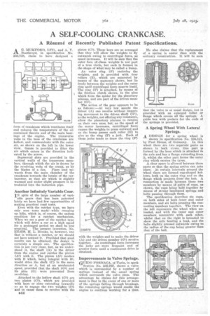
form of crankcase which ventilates itse f and reduces the temperature of the o I contained therein and of the main bearings of the engine. The transverse webs in the base of the crankcase are hollow, and communicate with the outer air, as shown on the left in the lower view. Gauze is provided to filter the air which enters in the direction indicated by the arrow.
Segmental slots are provided in the vertical walls of the transverse members, through whieh the air is drawn by the revolving webs of the crank, as by
the blades of a fan. Pipes lead upwards from the main chamber of the crankcase towards the intake of the carburetter, so that air which is slightly warmed and under slight pressure is introduced into the induction pipe.
Another Infinitely Variable Gear.
IN spite of the large number of variable gears that has been patented lately we have had few opportunities of making practical road tests.
Even with the ratchet type, we have only seen tests made' while creeping up hills, which is, of course, the easiest condition for a ratchet mechanism. When we see a gear of the ratchet type which will drive a car at a high speed for a prolonged period we shall be less
sceptical. The present invention, No. 235,639, H. L. Brooks, is, however, one that is without a ratchet, or we should not have noticed it. Provided that good results can be obtained, the design is certainly a simple one. The specification is not very clear, but, as we understand it, the shaft (A) is the driver from the engine and carries the pinion (A1) with it. The pinion (Al) meshes with B which, being integral with jai, would drive the shaft (C) in the same direction as A, but at an accelerated speed, provided that the shaft (G1) and its pins (G) were prevented from revolving.
Attached to the hollow shaft (C1) are two plates (C2), which are provided with keys or slots extending inwardly an as to engage the two weights (D) and to cause them to revolve with the
plates (C2). These keys are so arranged that they will allow the weights to fly outwards owing to centrifugal force, as speed increases. It will be seen that the outer face of.these weights is not part of a true circle, but each is formed in the shape of what may he called a bump.
An outer ring (F) encircles the weights, and is provided with four rollers (E), which are separated by means of the segments shown, but lie freely between the weights and the outer ring until centrifugal force asserts itself. The ring (P) is attached, by means of the friction clutch shown, to the pins which form the spider for the planetary pinions, and are part of the driven member (G1).
The action of the gear appears to he as follows :—At very low speeds the driver (A) can revolve without imparting movement to the driven shaft (G1), as the weights, not offering any resistance, allow the planetary pinions to revolve on their own axes, but, as the speed of the motor increases, centrifugal force causes the weights to press outward and as the bump passes each roller (E) to give to the ring (F) a jerk. Each of these jerks tends to draw the ring (P)
with the weights and to make the driver (A) and the driven member (G1) revolve together. As centrifugal force increases the jerks get more frequent and of greater force until a continuous drive is obtained.
Improvements in Valve Springs.
GUIDO FORNACA, of Turin, in speck
fication No. 235,767, shows a valve which is surrounded by a number of springs instead of the usual spring which surrounds the valve stem. The advantage he claims for this arrangement is that in the event of one or more of the springs failing through breakage, the remaining springs would enable the engine to continue working for a time. He also claims that the replacement of a spring is easier than with the ordinary construction. It will be seen that the valve is ot usual design, but provided with an enlarged collar or flange which covers all the springs. A guide box with pockets for the ends of the springs is provided.
A Spring Wheel With Lateral Springs, A DESIGN for a spring wheel is
shown in specification No. 235,121, by Paul Henss. of Germany. In this wheel there are two separate parts as shown in both views. One part is formed by the boss which is attached tb the axle and has a flange extending from it, whilst the other part forms the outer ring which tarries the tyres..
A clear space is allowed between these parts so that the spring action can take place: At certain intervals around the wheel there are formed cup-shaped hollows, both on the outer ring and on the flange which projects from the hub. A Connection is made between these two members by means of pairs of cups, as shown, the cups being held together by means of strong lamiliated springs and bolts passing through them. • The specification describes six cups, on both sides of both inner and outer members, and six bolts pressing the connecting members together. The view on the left represents the wheel when unloaded, and with the inner and outer members concentric with each other, whilst that on the right is intended to show the axle bearing a load, and the balls slightly pressed outwards owing to the radius of the cup being greater than that of the ball.