


Patents Completed.
Page 20
If you've noticed an error in this article please click here to report it so we can fix it.
Complete specifications of the following patents will be sent to any address in the United Kingdom upon receipt of eightpenee per copy at the Sale Branch, Patent Office, Holborn, W.C.
DRIVING CHAINS.—Hill and The Coventry Chain Co. (1907), Ltd.—No. 19,749, dated 28th August, 1909.—Ac. cording to this invention, the links of the driving chain are of " 11 " type; they may be of any desired pitch. The links are assembled together, so that each link is in a reverse direction to the adjacent one, that is to say, one link is of U form, while the next is an inverted " U," and so on. The links are secured together by means of rivets, which are free to revolve so as to ensure the chain's being flexible. Each link may be composed of one or more U-shaped links placed side by side. It will thus be seen that the chain may easily be made up to any desired length or width. The arrangement above described allows of the chain's being used on either side.
SELF PROPELLED COMBINED PLOUGHING AND MOWING MACHINES.—Waller.—No. 16,335, dated 13th July, 1909, and cognate Provisional No. 2,194, dated 28th January, 1910.— This invention relates to an improved agricultural implement, combining in an effective manner a self-propelled mowing machine, a self-propelled plough, a self-propelled tractor and a stationary engine. The main frame of the vehicle is provided with two steering wheels, operated in the usual manner, and two driving wheels, which receive motion from a countershaft by means of spur or other suitable gearing. The countershaft is divided into two parts and has its axis in the same plane as the axis of the longitudinally-disposed driving shaft. Each part of the said countershaft receives an independent motion from the driving shaft by means of a pair of bevel wheels and bevel pinions, the latter of which are loosely mounted on the driving shaft and are capable of being locked thereto by clutches which may be controlled by any suitable mechanism. The driving shaft receives its motion from the crankshaft of the engine through a change-speed
gear, which gives two forward speeds and one reverse. The attachment for carrying the mower consists of a frame pivoted to the side of the main frame, and the mechanism for imparting motion to the cutters of the mower, which latter is of the usual type, consists of a flexible shaft driven from the driving shaft by means of a chain gear ; control is effected by means of a clutch. The attachment for supporting the plough consists of two transversely-disposed shafts carried at the rear of the main frame of the implement. On these shafts are mounted bell-crank levers, and the frame of the plough is carried at their long ends, the short ends of the levers being connected together by links. The plough is raised or lowered to the ground by a chain, which passes over a winding drum on the main shaft. The transverse shafts are carried at one side in vertical slots, PO that, when the tractor is travelling with one wheel in a furrow and the other rn unploughed land, and is thus inclining to one side, the plough can assume a vertical position. A helt pulley is secured to the end of the driving shaft to transmit power to such machinery as chaff cutters or the like.
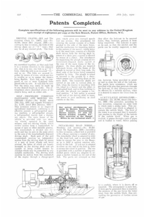
DETACHABLE ROAD WHEEL.— ltau.dslay and Another.—Nn. 20,453. dated 7th September, 1900.—Aceording to this invention, a fixed hub is provided with a flange carrying a number of pins. The detachable wheel is adapted to slide on the fixed hub, and is provided with holes to engage the pins on the flange, so as to hold it against rotation relatively to the hub. A lock-nut is adapted to screw on the end of the hub in order to secure the wheel in position. The nut is provided with anumber of spring-controlled pawls which are adapted to engage a ratchet formed on the end of the huh. The pawls are arranged so that
they allow the lock-nut to be screwed home; they, however, prevent it from being unscrewed. The lock-nut is open at its end, so that the ratchet and the pawls can be readily inspected, a dust
cap, however, being provided to screw on and to close the end of the lock-nut. The pawls have extensions, which are provided with pins that protrude through the lock-nut, so that disengagement can be effected by e suitable spanner, when it is desired to remove the wheel from its hub.
ACETYLENE GENERATORS.— Wakefield.—No. 23,195, dated 11th October, 1909.—The generator, according to this invention, comprises an outer tank in which rests a sludge tank. This carries a vertical cage which is adapted to contain the carbide block. The level of the water is so arranged that it normally just reaches to the height of the bottom of the carbide block. When gas is evolved, it passes through a pair of pipes and is washed in water, thence passing to a conduit, where it is drawn off as required. The arrangement is such that., if more gas be generated than is required, the pressure of the gas forces the water away from the carbide block, thus preventing the generation of further excess of gas.