


A New Duplex-Jet Carburetter.
Page 14
Page 15
If you've noticed an error in this article please click here to report it so we can fix it.
Very-numerous attempts have been made, from time to time, to secure increased elasticity of action on the part of carburetters, by the embodiment in the design of some arrangement of multiple jets. Several of these have justified the theories of their de e signers, and have, in consequence of reduced spirit consumptions, received a considerable welcome from users and manufacturers of motor vehicles.
On the present occasion, we have to deal with a new form of vaporizer— The Solex—in which, whilst its construction embodies the use of two jets, the method of coupling the secondary one is quite novel. Our attention has been drawn to the records of a number of remarkable petrol-consumption tests, which have been achieved with the aid of Solex carburetters that have been fitted to the engines of commercial-motor vehicles. So far, such fittings have only been made, to any extent, on motorbuses and on motorcabs, but the striking economies which have been effected in these instances clearly warrant a description by us of the mechanical arrangement by which the savings have been secured. The firm which is handling the Solex carburetter in this country is Messrs. S. Wolf and Co., of 1.38, Southwark Street, S.E., and we are informed by them that ius features, which have directly contributed, under practical working conditions, to the remarkable savings in. the consumption of spirit, are the combination of a special form of throttle valve with the final outlet of the auxiliary jet; the manner in which this throttle valve is mounted, and, finally, the provision of a small carefully-weighted ball valve, by which the vacuum round the auxiliary jet is modified when certain conditions of the engine's running so require.
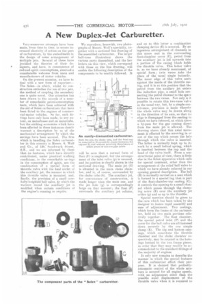
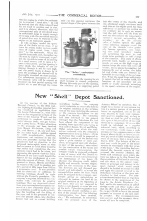
We reproduce, herewith, two photographs of Messrs. Wolf's speciality, together with a sectional line drawing of the assembled carburetter. The larger half-tone illustration shows the various parts dissembled, and the key letters on this view, which correspond with those on the line drawing, will enable the following description of the components to he readily followed. It will be seen that a normal form of float (E) is employed, but the arrangement of the inlet valve (p) is unusual, and its position is clearly shown in the sectional drawing. The main jet (C) is situated M the main choke chamber, and is, of course, surrounded by the choke tube (S). The auxiliary jet, for convenience of construction, is made longer than the main one, and the jet hole (g) is correspondingly large on that account ; the float (F) surrounds the auxiliary jet column, and on to this latter a combination clamping device (E) is screwed. By an ingenious arrangement of channels in this screw and in the surrounding float-chamber cover (C), petrol from the auxiliary jet is led upwards into a portion of the casing which holds the throttle valve. This latter valve is, as we have already mentioned, of special form ; twin vanes take the place of the usual single butterfly. The inner edge of this valve seats against the inside of the throttle easing, and it is at this position that the petrol from the auxilary jet enters the induction pipe, a small hole connecting the petrol channel to the space between the two vanes. Not only is it possible to rotate this two-vane valve in the usual way, but, by a simple contrivance, provision is made whereby the whole valve may be drawn along in the direction of its axis, so that its edge is disengaged from the seating to which we have referred, at which times a by-pass for the gas coming direct from the main jet is allowed_ The drawing shows that this axial movement is effected by the screwing in or out of the cap which covers the hole through which the valve is inserted. The latter is normally kept up to its work by a small helical spring, which is inserted between the cap and the head of the valve itself. From a constructional point of view, there is little else in the Solex apparatus which calls for special comment, other than the arrangement of the relief ball valve to which we have already referred in our opening general description. The ball (II) is normally carried on a seat which is formed in a, special lug that is part of the float-chamber-top casting (C) ; it controls the opening to a small channel which passes through the clamping screw (E) over the auxiliary jet orifice (g) and so up to the throttle.
Special mention should be given to the care which has been taken by the designer to insure rapid assembly and ease of adjustment. Two castings, which form the frame of the carburetter, hold its two main portions relatively together. The float chamber, the special petrol inlet (P) and the cover for the ball valve are all fastened down securely by the one simple clamp (E). The top and bottom castings, which constitute the throttle chamber and the choke chamber respectively, may be rotated in the housings formed by the two frame pieces, in order that they niay readily he accommodated to the standard fittings of the majority of engines.
It only now remains to describe the manner in which the special features of this carburetter effect their purpose. It is claimed that perfectlyautomatic control of the whole mixture is secured for all engine, speeds, with no adjustment other than the possible axial displacement of the throttle valve when it is required to
run the engine to which the carburetter is attached dead slow." It will he noticed that the choke tubes (S and K) are fixed in position and in size, and it is obvious, therefore, that the cross-sectional area of this detail must be sufficiently large to supply enough air to mix with the maximum amount of petrol that may be required by the engine at its maximum speeds. It will, perhaps, render the operation of the Soles device clear, if we trace its action under various conditions of engine speed, from " dead slow " to the maximum. When the throttle is entirely shut, the milled cap (B) must be slightly unscrewed, to permit the throttle to come off its seating to a small extent, and to open a hepass at that point. As this opening is quite small, the velocity of the air passing through it will be very high, and the petrol which is drawn by it from the auxiliary jet channel will be thoroughly atomized on that account. For subsequent increments of speed, the throttle valve will be rotated as required its first partial opening will permit air to pass through the vanes
only; as this opening continues, the special shape of the space between the varies provides that the opening for air shall increase in correct proportion. During this early part of the opening, the auxiliary jet is supplying petrol into the centre of the throttle, and this additional supply continues until such time as the engine speed has risen stifficiently to increase the suction on the auxiliary jet to such an extent that the bail valve will lift from its seat and thus relieve the temporarilyexcessive vacuum surrounding the secondary jet. As the throttle valve is further opened, the additional induction passages round the sides of the throttle valve gradually become operative, thus relieving the local secondary tension and permitting the main jet and choke tube gradually to take charge of the situation. This state of affairs proceeds until, finally, at maximum speeds, as awn as the high stage of tension keeps the relief ball valve off its seat, and so places the auxiliary jet temporarily out of action, the main jet and choke tube are entirely responsible for the whole of the carburation. When the speed drops sufficiently to permit the ball to reseat itself, the functions of the secondary jet are partly or wholly resumed, according to the speed variations of the engine.