


A LIGHT SIX-WHEELER
Page 52
Page 53
If you've noticed an error in this article please click here to report it so we can fix it.
with Semi-forward Control
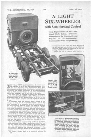
Many Improvements in the Latest Model V.S.W. Vulcan. Articulated Suspension at the Front, Additional Support for the Supplementary Gearbox and a Better Design of Bogie THE Vulcan V.S.W. model rigid-frame six-wheeler was first described by us in our issue dated February 15th, 1927, but since that time many improvements have been effected and, in its latest form, it can almost be classified as an entirely new chassis, particularly as it is now arranged with the W.D. standard design of cab giving semi-forward control and allowing a seat at each side of the engine.
This light model is designed to comply with War Office Specifications Nos. 31 and 23E, and for W.D. purposes it is arranged to carry 20 cwt. across country, or 30 cwt. on the road, but for civilian purposes it is fully capable of carrying 2 tons.
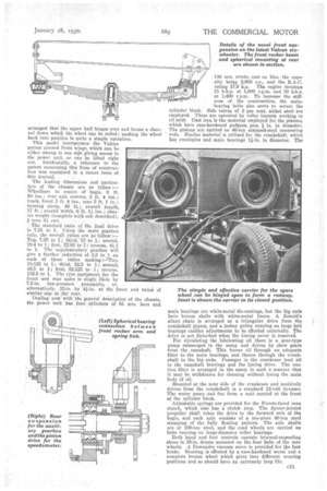
As compared with the original model, certain of the changes in design are of considerable interest. One of the most important is in connection with the arrangement of the front springing, which is given a high degree of articulation, although ordinary semi-elliptics are employed. At the front each is connected through a spherical mounting to a centrally pivoted rocker beam, whilst at the rear the ordinary shacklepin is also replaced by a spherical mounting.
To remove the engine it is merely necessary to lift the forward dash by unscrewing two nuts at each side, unbolt the front cross-member and bring into action the special jacking devices on the front springs which take the load When the front point of support is removed. Then the engine and the gearbox can be lifted out through the front without any difficulty.
At the rear of the supplementary gearbox is an articulated suspension which takes a good proportion of the load and thus relieves the other mountings of the engine gearbox unit. An important feature is that the frame flanges are not chilled for securing the radius-rod anchorage. This cross-member is bolted to flanges on the bogie-spring fulcrum brackets.
To enable a longer shaft to be employed between the arranged that the upper half hinges over and forms a channel down which the wheel can be rolled ; pushing the wheel back into position is quite a simple operation. This model incorporates the Vulcan patent pivoted front wings, which can be. either swung to one sift giving access to the power unit, or can be lifted right out. Incidentally, a reference to the patent concerning this form of construe-. tion was contained in a recent issue of this .journal.
The leading dimensions and particulars of the chassis are as follow:— Wheelbase to centre of bogie, 9 ft. 10 ins. rear axle centres, 3 ft. 4 ins.; track, front 5 ft. 4 ins., rear 5 ft. 1 in.; turning circle, 45 ft.; overall length, 17 ft.; overall width, 6 ft. 1i ins.; chassis weight (complete with cab described), 2 tons 9i cwt. .
The standard ratio of the final drive is 7.25 to 1. Using the main gearbox only, the overall ratios are as'follow :— Top, 7.25 to 1; third, 18 to .1.; second, 19.4 to 1; first, 32.85.to 1 ; reverse, 41.1 to 1. The supplementary gearbox will give a further reduction of 2.5 to 1 on each of • these ratios making :=Top, 18.125 to 1; third, 32.5 to 1; second, 48.5 to 1; first, 82.125 to 1; reverse, 102.5 to 1. Tile tyre ,equipment for the front and rear, axles is single 34-in by 7.5-in, low-pressure pneumatic, or,
alternatively, 32-in. by 'at the front and twin S of similar size at the' rear. .
Dealing now with the general description of the chassis, the Power unit has four cylinders Of 85 mm. bore and 130 mm. stroke cast en bloc, the capacity being 2,950 c.c., and the R.A.C. rating 17.9 h.p. The engine develops 21 b.b.p. at 1,000 Lam. and 30 b.h.p. at 1,400 'r.p.m. To increase the stiffness of the construction, the mainbearing bolts also serve to secure the cylinder block. Side valves of 3 per cent. nickel steel are employed. These are operated by roller tappets working in oil mist. Cast iron is the material employed for the pistons, which have ease-hardened gudgeon pins .1 in. in diameter. The pistons are catried on 40-ton stamped-steel connecting rods. Similar material is utilized for the crankshaft, which has crankpins and main bearings II-in. in diameter. The main bearings are white-metal die-castings, but the big ends have bronze shells with white-metal liners. A Renold'a silent chain is arranged as a triangular drive from the crankshaft pinion, and a jockey pulley running on large ball bearings enables adjustments to be effected externally. The drive is not disturbed when the timing cover is removed.
For circulating the lubricating oil there is a gear-type pump submerged in the sump and driven by skew gears from the camshaft. This forces oil through an adequate hlter to the main bearings, and thence through the crankshaft to the big ends. Passages in the crankcase lead oil to the camshaft bearings and the timing drive. The suction filter is arranged in the sump in such a manner that it may be withdrawn for cleaning without losing the main body of oil.
Mounted at the near side of the crankcase and positively driven from the crankshaft is a standard 12-volt dynamo. The water pump and fan form a unit carried at the front of the cylinder block.
Adjustable springs are provided for the Ferodo-faced cone clutch, which also has a clutch stop. The Spicer-jointed propeller shaft takes the drive to the forward axle of the bogie, and each axle consists of a one-piece 40-ton steel stamping of the fully floating pattern. The axle shafts are of 100-ton steel, and the road wheels are carried on hubs running on large-diameter roller bearings.
Both hand and foot controls operate internal-expanding shoes in 16-in, drums mounted on the four hubs of the rear -wheels. A Dewandre vacuum servo is provided for tie foot brake. Steering is effected by a case-hardened worm and a complete bronze wheel which gives four different wearing positions and so should have an extremely long life.