


Novel Features in a Six-wheeler Conversion Set
Page 47
If you've noticed an error in this article please click here to report it so we can fix it.
OWNERS of four wheeled venicles and prospective purchasers of chassis are today paying inereashag attention to the possibilities of the conversion sets which are offered for the purpose of turning f ourwheelers into rigid six wheelers. A particularly interesting example is
the Flexion, patented and manufactured by C. H. and L. O. Smith, Ltd., Canal Street, Nottingham; the works are at Beeston, Notts.
The Flexion attachment can be supplied for any make of chassis ; as a rule 75 per cent, of the parts used are standard products of the chassis builder, thus permitting quick replacement in service. It was first patented in 1927 and since then the design has been exhaustively tested in Great Britain and South America, loads of eight tons and over having been carried.
An example which we inspected and photographed at Beeston was built into a standard Chevrolet 30-cwt. chassis. In this description we allude to the machine in question, but the particulars are applicable to other chassis. When cenverted the Chevrolet will carry a 2/-ton pay-load, the annual tax is 125 and the cost of the conversion set is 1S7 10s. If an independent brake upon the dead trailing axle be required the additional costis 17 10s.
Dealing first with the frame : the main members are extended to give the body space that is required. Hightensile-steel channel is used, this being Excel to the end of the existing chassis, whilst liners are used internally. The end of the extension is closed by a cross-member with diagonal bracing straps. The rear of the frame is supported at three points on each side. This design, owing to its small length of unsupported frame, permits the use of a tipping body. Loading space up to a length of 14 ft. can be Provided. The wheelbase
of the bogie is 3 ft. 1 in., whilst the wheelbase to the centre of the bogie is 12 ft. 51 ins. When a 12-ft. pay-load length is specified the overall dimension is 19 -ft. 7/ ins.
A standard rear-axle casing forms the basis of the added trailing axle; half -shafts are employed, but there is DO differential. The drive. is through only the intermediate axle. Standard Chevrolet wheels with 32-in. by 6-in. tyres are provided, Much interest attaches to the suspension system, which has been designed with the object of giving the maximum degree of insulation to the chassis over surfaces which cause considerable relative movements of the axles of the . bogie, in addition to tilting action. The forward portions of the springs on the intermediate axle take the driving stresses, as in the standard Chevrolet chassis.
The forward ends of both pairs of springs are anchored
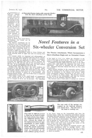
to the frame ; those on the intermediate axle have the standard fixing, whilst the underslung semi-elliptic springs (standard Chevrolet pattern) of the trailing axle are secured to the previously mentioned pendant brackets, which are braced to the frame side-members. The, rear ends of each pair of springs on the same side are coupled by a built-up steel balancer arm, which pivots on ball bearings. Abutment plates with limit stops regulate the action of the balancer arms and take lateral loads.
In 'order to relieve the springs of torsional stresses, the barrel-type shacklepins work in paraIIcl bushes. The springs of both axles of the bogie are in line and, as there is considerable overlap, the wheelbase of the bogie is kept as short as possible.