• A CONVERT TO THE THIMBLE TUBE BOILER.
Page 15

If you've noticed an error in this article please click here to report it so we can fix it.
Details of the New Boiler which is being Utilized on the Leyland Wagon.
THERE IS no doubt that many readers Of this journal will have noted thatin connection with a resent iflustration portraying a steam wagon wiich formed the exhibit of Leyland Motors, Ltd., at the Royal Lancashire Show, we referred to the fact that this wagon, which is the latest type made. bythe company; embodies a thimbletube boiler. This is a particularly interesting innovation on the Leyland machines, as it shows an important trend in. steam-vaagon design. •
It will be remembered that this type of boiler has long been advocated by Mr. Thomas Clarkson, and some little time ago there was, a large amount of correspondence in the columns of this journal devoted to " Opinions from Others" regarding the efficiency and probable life of steam producers of this type. Such a well-known company as the buihiers of the Leyland vehicles would not be likely to make use of components which might show, or eventually develop, any signs of weakness, and as the thimble-tube boiler has progressed beyond the experimental stage on their wagons, it is apparent . that it has received their approbation.
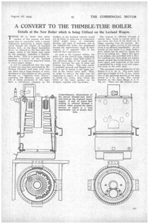
As used in the Leyland vehicle, the boiler is of the Vertical type, comprising a straight, tubular outer shell bolted to the upturned edge of the coned `centre portion carrying the nest of tubes and forming the firebox. The tube carrier is extended upwards and flanged over so that it can be bolted to the upper portion of the tubular Outer shell. Thus, in order to remove the, tube cone for inspection or repair, it is only necessary to break two joints, after which the whole of the inner portion can be dropped, together with the firebox.
The stoking. is effected through & central tube, which is carried down to just below the level of the third row of tubes, counting from the bottom. Encircling the, upper portion of the stoking chute is an efficient superheater. At the bottom of the 'boiler is a large firebox door, which can be used for laying the fire or for raking out-. Below this again is an ashpan, 'also provided with a door. For washing out-, three plugs are equally spaced around the lowest portion of the water space, and inspection of the tubes is permitted by a large cover and inspection holes in the outer shell.
The maximum internal diameter of the firebox is 2 ft. (4 in. The main outer
shell has a height of 2 ft. ins., whilst that of the upturned portion of the tube carrier is 1 ft. 2 ins. The overall diameter at the. main flange is 2 ft. 10i ins. There are 128 thimble tubes.


