


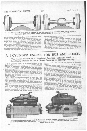
A 6-CYL1NDER ENGINE FOR BUS AND COACH.
Page 14
Page 15
If you've noticed an error in this article please click here to report it so we can fix it.
The Latest Product of a Prominent American Company, which is Specifically Intended for Use in Chassis Employed for Passenger-carrying.
A'"ricgenerally known, it is common practice inthe Ame an motor industry to assemble vehicles from the products of companies specializing in the manufacture of definite components. This procedure has been extensively adopted, with the result that many organizations have been formed and developed for the express purpose of manufacturing and supplying such essentials as engines, clutches, gearboxes, back axles, frames, wheels, etc., many of which are widely used in chassis of American origin, and also, to a lesser degree, in chassis produced in other countries, including our own.
It is not our object on this occasion to enter into a discussion on the pros and cons of this policy, but it has certainly enabled the actual producers of chassis to be spared a lot of experimental work and, at the same time, to be in a position to secure components of approved and satisfactory types.
So far as engines are concerned, one of the best-known range in the United States is that produced by the Buda Co., of Harvey, Illinois, and in so far as this company are directly represented in England at 75, 'Evershot Road, Stroud Green, London, N.4, we are justified in dealing with the new model which has just been produced in the parent factory.
The new engine, which is known as the GL-6, possesses a close resemblance to the company's bus-type engine, which was produced a little while ago, and briefly dealt with by us, but it incorporates one or bet) notable differences. In the first place, the cylinder dimensions are somewhat larger, for the GL-6 engine has a bore of 41 ins, and a stroke of 6 ins., as compared with a bore of 4 ins, and a stroke of 5i ins. of the other model. In the case of the GL-6 model, too, four-bolt connecting rods are used instead of two, as in the case of the other model, and a full-floating pin with a drilled hole through the rod for lubrication purposes is another respect in which it differs.
We will now proceed to a brief description of the outstanding features of the GL-6 engine, which, we should add, has been specifically designed for niotor coach and similar passenger-vehicle uses. The engine is a six-cylinder, with its cylinders cast en bloc, and it has a removable head, which is provided with a liberal water space above the combustion chamber, slightly, tapered towards the header in order to ensure an unrestricted flow of water to the outlet. The valves are of good size, and are operated by a single camshaft. They are entirely enclosed, but a cover in three sections facilitates inspection and permits easy adjustment of the tappets. The valves are all operated by barrel-type, self-centring, alloy-steel springs, which eliminate thrust on the stems. The valve push rods are of the mushroom type,• and, being of a good size, permit the use of large-diameter adjusting screws so as to maintain alignment.
The pistons are fitted with three concentric rings above the wrist pin and a scraper ring below, and are provided with cooling ribs to assist in the dissipation of the heat which is generated. The connecting rods are drop forgings of chrome-vanadium steel, and are of I-beam section. Their upper ends are fitted with phosphor-bronze bushings, and the lower ends with bronze shell, babbit-lined bearings.
The crankshaft is of Unusually heavy construction for this size of engine, and is drilled for lubrication purposes. It is 21. ins, in diameter, and the connecting-rod bearings and the front three main bearings are of the same length and diameter, whilst the rear bearing is a little longer in order to carry the additional load and torque. The rear end of the shaft has two oil throwers, so that leakage into the bell-housing is prevented, and this end of the shaft is also provided with a flange to which the flywheel is bolted.
The camshaft is a drop forging, and a flange to which the timing gear is bolted is made integral with the shaft.
The timing gears are of 11-in, face and have helical teeth. The gears are very accessible upon removal of the gearcase cover, which is arranged with a large trunnion forming the third support for the engine, and to which the starting crank bracket is also bolted. The other two points of support are by strong arms cast integral with the upper half of the crankcase at the rear.
The crankcase is of aluminium alloy. It is well reinforced and filleted where the greatest stresses are present. It is divided horizontally 4 ins, below the centre of the crankshaft. The upper part contains the crankshaft and camshaft bearings, and extends over the flywheel to form the upper part of the bell-housing. For draining the oil a liberal-size cock is provided.
The lubrication system is a patent of the Buda Co. Oil is force-fed to the main bearings and camshaft bearings through a seamless-steel distributing pipe cast in the crankcase, and from the main bearings to the connecting-rod bearings through a drilled passage in the crankshaft. The oil is pumped from a reservoir below the crankcase by a geartype pump located at the rear and attached to the upper half of the crankcase. The pump is provided with a suitable screen around its inlet to prevent foreign particles entering the circulating 'system.
The pistons and cylinder walls are lubricated by oil thrown from the lower ends of the connecting rods, whilst the timing gears are fed from the relief valve of the pressure system.
For cooling the engine the water is circulated by a ceutri
fugal pump with a bronze runner, and the pump shaft is provided with a bronze sleeve in order to prevent rusting and pitting.
The fan-bracket support is cast integral with the crankcase, and a fan pulley for a V-belt is attached to the pump gearshaft ahead of the gearcase cover, where it is readily accessible when the belt has to be renewed or repaired.
Provision is made for the use of a magneto driven from the water-pump shaft, or battery ignition by timer, which can be mounted on the pump drive-shaft housing. Suitable accommodation is also available for fixing starting and lighting equipment.
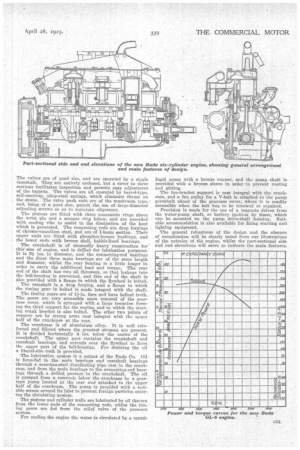
The general robustness of the design and the absence of complication will be clearly noted from our illustrations of the exterior of the engine, Whilst the part-sectional side and end elevations will serve to indicate the main features.