


A NEW HEAVY-DUTY LORRY CHASSIS.
Page 9
Page 10
If you've noticed an error in this article please click here to report it so we can fix it.
Details of the New 6-ton Worm-driven Berliet Chassis Showing the Differences Between It and the 5-ton Model.
THE name of Berliet has for many years past been 1 connected with heavy-duty vehicles of robust design and construction, and large numbers of their machines are in daily use both an this country and abroad.
Their 5-ton chassis is perhaps the best-known of their products, and has been the standard heavy-duty lorry of the French Army since pre-war days. During the war some 22,000 of this model were supplied to the Allied Governments, and, although the design has remained practically unaltered, various detail improvements have been embodied in the 1925 production which is described in this article.
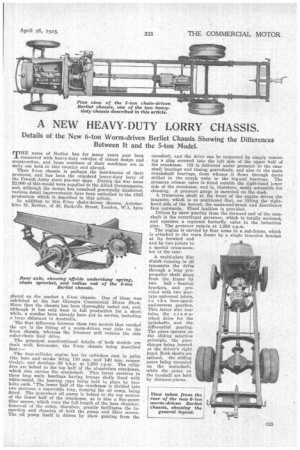
In addition to this 5-ton chain-driven Chassis, Automobiles M. Berliet, of 40, Sackville Street, London, W.1, have placed on the market a 6-ton chassis. One of these was exhibited at the last Olympia Commercial Motor Show. Since then the chassis has been thoroughly tested out, and, although it has only been in full production for a short while, a number have already been put in service, including a large shipment to Australia.
The first difference between these two models that catches the eye is the fitting of a worm-driven rear axle on the 6-ton chassis whereas the 5-tonner still retains the side roller-chain final drive.
The principal constructional details of both models are dealt with hereunder, the 5-ton chassis being described first:—
The four-cylinder engine has its cylinders cast in pairs (the bore and stroke being 110 mm. and 140 ram. respectively), and develops 36 b.h.p. at 1,250 r.p.m. The Cylinders are bolted to the top half of the aluminittm crankcase, which also carries the crankshaft. This latter revolves in three long main bearings having bronze shells lined with white-metal, the bearing caps being held in place by four bolts each. 'The lower half of the crankcase is divided into two sections, a removable tray, forming the oil sump, being fitted. The gearwheel oil pump is bolted to the top section of the lower half of the crankcase, as is also a fine-gauze filter screen, which runs the full length of the base chamber. Removal of the sump. therefore, greatly facilitates the inspection and cleaning of both the pump and filter screen. The oil pump itself is driven by skew gearing from the camshaft, and the drive can be inspected by simply removing a plug screwed into the left side of the upper half of the crankcase. Oil is delivered under pressure to the camshaft bearings and timing gearwheels, and also to the main crankshaft bearings, from whence it flows through ducts drilled in the crank, webs to the big-end hearings. The pressure release valve is fitted outside the right-hand lower side of the crankcase, and is, therefore, easily accessible for cleaning. A pressure gauge is mounted on the dash.
A transverse shaft at the front of the engine drives the magneto, which is so positioned that, on lifting the righthand side of the bonnet, the make-and-break and distributor face Outwards. Fixed ignition is provided.
Driven by skew gearing from the forward end of the camshaft is the centrifugal governor, which is totally enclosed, and operates a separate butterfly valve in the induction pipe. The governor cuts-in at 1,250 r.p.m.
The engine is carried by four arms in a sub-frame, which is attached to the main frame by a single trunnion bracket at its forward end and by two points to a special cross-member at the rear.
A multi-plate disc clutch running in oil transmits the drive through a long propropeller shaft slung from the frame by two ball bearing brackets, and provided with two startype universal joints, to the four-speedand-reverse gearbox. This latter also contains the crownwheel drive for the iackshafts, and the differential gearing. The gears operate on the sliding selective principle, the gatechange being located at the driver's right hand. Both shafts are splined, the sliding gears being mounted on the rnainshaft, while the gears on the layshaft are held by distance-pieces.
The drive from the mainshaft to the jackshafts is by straight-toothed bevel and crown wheel, the latter being bolted to the easing of the four-pinion differential. The differential casing extends outside the gearbox casing, and the foot-brake drum is mounted on a taper turned on the near-side extension, being held in position by a key and locknut. The foot brake is of the external-contracting type, the shoes having cast-iron liners.
The jackshafts are splined at their inner ends, whilst the small chain sprockets are mounted on a taper at their outer ends by means, of a key and nut. The side-members of the chassis are drilled to allow the jackshafts to pass through, brackets bolted to the outer side of the chassis members housing the ball races which carry the jackshafts.
These brackets also serve as the forward anchorage for the adjustable radius rods. The radius rods are constructed in three parts—the forward part haz a large eye bushed with a bronze bush, which encircles the jackshaft bracket, and on the tail of this eye is mounted a bronze screw with a hexagon head, which screws into the rear half of the radius rod. This screwed portion provides the adjustment for the driving chains, and is locked in position by a long bolt, which tightens the split upper end of the rear part of the radius rod. The rear end of the radius rod is mounted on the rear axle, and is provided with a bronze bush, whilst the rearmost point of the rod carries the, handbrake cam-operating rod. The rear-brake shoes are pivoted to the radius rod at a point in front of the rear axle.
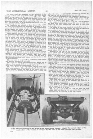
The rear axle itself is a square forging of large section, having its ends turned to carry the ball races on which the cast-steel rear" wheels are mounted. The large chain sprockets are bolted to the rear wheels, and the shoes of the internal-expanding hand brakes bear in the inner side of these sprockets.
The rear axle is suspended by underslung semi-elliptic rear springs, shackled at each end.
The total gear ratios from engine to rear wheels are as follow :—First speed, 48.48 to 1; second speed, 28.41 to 1; third speed, 16.53 to 1; fourth speed, 9.87 to 1.
The main frame is of deep-section channel steel with seven cross-members. The underside of each frame member tapers upwards towards the front of the vehicle, while the side-members are inswept at the front from it point just below the dash. A spring-loaded drawbar is provided at the rear, as well as towing hooks fore and aft The principal dimensions of the chassis are as follow:— Overall length, 22 ft. 4 ins.; overall width, 7 ft.; clash to end of frame, 16 ft. 2 ins.; wheelbase, 13 ft. 9 ins.; track,
front, 5 ft.-10 ins.; rear, 5 ft. 7 ins. ,
The weight of the bare chassis is 63 cwt., and the wheels are shod with solid-rubber tyres, 950 mm. by 140 mm. singles on the front wheels and 1,030 mm. by 160 twin tyres at the rear.
The engine of the 6-ton chassis is identical in every respect with that of the 5-ton -model, and there is, therefore, no necessity to go over this component again.
A multi-plate dutch conveys the drive by means of a short cardau shaft, in which is embodied an alignment joint, to the four-speed-and-reverse gearbox. The general construction of the gearbox is similar to that of the 5-tonner, except, of course, that the differential gearing and jackshafts are not embodied therein. Central change is employed, the gear lever and selector mechanism being carded on the forward end of the gearbox. The gearbox is fourpoint suspended. The gearbox mainshafi is extended to the rear outside the gearbox, and is provided with a taper on which is mounted, by means of a key and nut, the ribbed drum of the internal-expanding foot brake.
The gear ratios are as follow :—First speed, 53.46 to 1; second speed, 32.87 to 1; third speed, 18.41 to 1; fourth speed (direct drive), 11 to 1.
Mounted on the rear of the foot-brake drum are three studs, which form the forward anchorage for the flexibledisc universal joint at the forward end of the open propeller shaft. The spider at the forward end of the propeller shaft is held in position on a taper by a key and nut, whilst the rear end of the shaft is splined, and fits into the forward spider of the flexible-disc universal joint at the rear end of the propeller shaft. The rear spider of the rear universal joint is held on a tapered extension of the wormshaft by a key and nut.
The rear axle is of the full-floating overhead worm and wheel type, with a four-pinion differential. The casing is a pot-type steel forging, the differential gearing being carried in brackets attached to the cover of the worm casing, which permits of its being entirely removed from the axle after the splined drive shafts are withdrawn. The cast-steel rear wheels revolve on ball bearings. The axle is suspended on underslung semi-elliptic rear springs, anchored at their forward ends and shackled at the rear, the torsion and driving strains being taken by the springs. The hand brakes operate on the rear wheels, and are internal.
The front axle, front springs and steering gear are of similar design to those of the 6-tonner, but naturally of slightly heavier construction.
The principal dimensions of the chassis are :—Overall length, 20 ft. 5 ins.; overall width, 6 ft. 91 ins.; dash to end of frame, 16 ft. 3 ins.; wheelbase, 13 ft. 9 ins.; track, front, 6 ft.; rear, 5 ft. 5 ins.
The chassis weight is 68 cwt. and the tyres are solidrubber single 950 mm. by 140 MM. on the front wheels and twin 970 min. by 200 mm. on the rear wheels.