


AN APPARATUS FOR TESTING MOTOR VEHICLES.
Page 70
If you've noticed an error in this article please click here to report it so we can fix it.
A Resume of Recently Published Patent Specifications.
mlIE specification No. 275,730, William Frost, points out
that, hitherto,i the testing of vehicles and their equipment had been effected by dealing with their components separately, such as brake tests for engines, or, if desired, by tests on public roads or special tracks, but there is a difficulty in obtaining any definite numerical value from such tests. It further points out that such tests are not always reliable, as the conditioa of roads and weather may vary and so reduce their value.
. The 'apparatus described consists of four wide drums set a suitable distance apart 80 that the rear wheels of a vehicle can run on them as they would on a road. One pair of these drums is mounted on a shaft which is provided with a sleeve carrying a crank at One end and .a friction clutch at the other end. The crank is prevented from making more than a partial revolution by a connecting rod, which is controlled by a strong spring. The vehicle is anchored from forward movement, so that its whole energy is transmitted to revolving drums. The speed at which the drums revolve is shown on an instrument which roay be calibrated to show miles or metres per hour. Pressure brought to bear on the clutch causes friction which extends the spring, and a cord wrapped round the sleeve indicates the energy being exerted on the spring. From these two figures the exact output of power, less frictional losses, can be obtained.
The Steering of Tractor-drawn Trains of Trucks.
FURTHER developments of the system (employed by Henri
Wouter Jonkhoff). of steering trains oftrucks drawn by a tractor are described in patent No. 275,704. The Commercial Motor has on several occasions dealt with the Jonkhoff system at length, and the present patent appears to cover material which lias been already described.
A Reversible Free Wheel.
THE subject of free wheels which can be reversed in their
action or can instantly be turned into a positive drive in both directions would seem to be occupying the attention of inventors at the moment. Probably, this is due to the new movement for providing a free wheel of this plass at the rear of the gearbox, in. order to make the change of gear more eaay. The specification of John Standen Shaw, No. 276,090, describes a free wheel of the kind, Rut the •special application described is not for the above purpose, but for use in
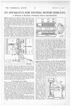
• Connection with a gear of the class where a reciprocating movement is transformed into a rotary motion by means of a number of free wheels mounted on the same shaft and rocked by means of cranks or eccentrics.
The sectional view on the right shows, roughly, the nature of the device, where a number of sloping surfaces bear against a number of rollers and jam them against an outer ring. So far there is nothing new, but it will be noticed that the 048 rollers bear not against the outer ring but „against a ring which is free to revolve within the usual cuter member. The longitudinal section shows six of these free wheels side by side on the same shaft, which is hollow, and is slidablo on the shaft which runs through it. It will be noticed that the six outer members are alternately provided with free rings inside the outer members. Only those rollers that come in contact with the outer member, without a free ring being interposed, are able to transmit power—those that bear against a free ring being inoperative.
As shown, the first, tiaird and fifth (counting from left to right) of the free wheels are-inoperative, whilst the second, fourth and sixth are operative. The free-wheel ratchets are placed on the shaft with their sloping surfaces alternately arranged, so, as shown, a reciprocating movement of the drums would cause the shaft to rotate in a forward direction, whilst, if the hollow shaft were moved to the right hand. the backward rachets would be brought into operation, and the forward ratchets would cease to act owing to the inter' position of the free rings. • 'Automatic Lubrication of the Clutch Bearings.
THE lubrication of the bearings which are associated with the clutch has always presented some difficulty as, unlike the more important beatings, they only need lubrication on somewhat rare occasions, therefore they are more likely to. be forgotten altogether. This is more than ever the case where unit construction is adopted. The specificatioti of John I. Thornycroft and Co., Ltd., and Tom Thorn ycroft, No. 276,06.3, describes a means whereby a slight stream of oil can be led from the gearbox to the spigot bearing and to • the bearing of the withdrawal mechanism.
The end of the gear shaft, shown on the right, ends just at the inner ring of the ball bearing. The clutch shaft, which carries the pinion, has a recess bored in it so that oil can find its way through the ball hearing and can enter the hollow clutch shaft A helical groove in the hollow shaft helps the oil to travel up it. On its ,,vIty a. certain amount can escape through the duct shown and lubricate the thrust bearing. The remainder of the oil can travel to the recess in the flywheel, where it can lubricate the spigot bearing. The feed must, of course, be carefully calculated. as any excess of supply to the spigot hearing would be liable to get on to the clutch surfaces.