


Patents Completed.
Page 26
If you've noticed an error in this article please click here to report it so we can fix it.
Abridgments of Interesting Specifications.
VENTILATION OF VEHICLES.— Esse.—No. 26,672, dated December 21st, 1905.—For the purpose of ventilating vehicles, the handrail, or other adaptable part of the vehicle, is made hollow and extended out to the front of the vehicle, where it may be provided with a funnelshaped or enlarged mouth (D). The
rail (A) is perforated at B throughout its length, so that the air entering by the enlarged mouth is dispersed throughout the vehicle. If desired the rail may be made rotatable, whereby the perforated portion may be brought into different positions. Perforations may be formed
by stamping down tongues from the wall of the tube : these tongues serve as baffles, and may be made shorter towards the near end of the tube, so that the air may be more evenly distributed.
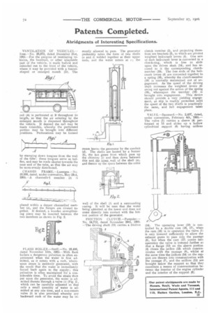
CHASSIS FRAME.—Lazerges.—No. 10,900, dated, under convention, May 23rd, 1905.—A channelled member . (6) is placed within a deeper channelled member (a) , and the flanges are riveted together. If desired, a wooden strengthening piece may be inserted between the two members as shown in Fig. 2.
FLASH BOILER.—SnelL—No. 23,486, dated November 15th, 1905.—With flash boilers a dangerous pulsation is often experienced when the water is first admitted, as it enters with a rush, whereupon steam is suddenly generated, with the result that the water is immediately forced back again to the supply ; this pulsation is often maintained for a considerable time. To avoid the strain thus put upon the generator, the water is admitted thereto through a valve (s) (Fig. 21, which can be carefully adjusted so that only a small quantity of water is admitted at any one time, and a non-return valve (1) is also provided whereby any backward rush of the water may be in stantly allowed to pass. The generator preferably takes the form of two shells (a and b) welded together at their upper ends, and the water enters at ; the steam leaves the generator by the conduit (d). The shells are heated by a burner 14), the hot gases from which pass up the chimney (e) and then down between this and the inner wall of the shell (a), and thence up the space between the outer wall of the shell (b) and a surrounding casing. It will be seen that the water being admitted at the lower end does not come directly into contact with the hottest portion of the generator.
FRICTION CLUTCH.—Pasquier.-No. 24,712, dated November 29th, 1905. —The driving shaft (15) carries a friction
clutch member (2), and projecting therefrom are brackets (3), to which are pivoted weighted bell-crank levers (4). One arm of each bell-crank lever is connected to a clutch-ring, which is free to slide upon the driven shaft (14), and has secured to it the corresponding clutchmember (10). The free ends of the bellcrank levers (4) are connected together to a spring (16), whereby the clutch-member (10) is normally maintained out of engagement, As the speed of the driving shaft increases the weighted levers (41 swing out against the action of the spring (16), whereupon the member (10) is
brought into engagement. This device should provide a very yielding engagement, as slip is readily permitted until the speed of the two shafts is practically the same, and full engagement takes place.
VALVE.—Saussard.—No. 2,457, dated, under convention, February 4th, 1905.— The valve (1) carries a sleeve (4) perforated at 15 and slides up a hollow cylindrical support (6) having orifices
(14). The operating lever (19) is controlled by a double cam (16, 17), when the cam (16) is in operation the valve (1) is only lowered sufficiently to allow the exhaust gases to pass into the passage (8), but when the cam (17) comes into operation the valve is lowered further so that a flange (12) on the sleeve portion (4) closes the orifice (13) which communicates with the passage (8), whilst at the same time the orifices (14) on the support are thrown into communication with the passage (7), and the orifices (15) are brought below the support so that they constitute a means of communication between the interior of the engine cylinder and the interior of the support (6).