


A NEW LOW LOAD-LINE DENNIS CHASSIS.
Page 44
Page 45
If you've noticed an error in this article please click here to report it so we can fix it.
Dennis Bros., Ltd., Bring Out a New 30 h.p. Model With 2-ft. Frame Height. Forward Dash, and Servo-operated Four-wheel Brakes.
MHE products of Dennis Brothers, Ltd., are so well
khown for their excellence of design and construction 'that particular interest attaches to new models brought out by this concern. The latest of their products is a low 1oad-line.30 h.p. chassis for bus service, in which the height of the frame from the ground, when loaded, is only 2 ft. This chassis is a new job throughout, including engine, gearbox and back axle, its interesting features being the low level, the forward dash, the fact that a straight line has been obtained for the transmission shafting, and the braking system. The last-named is of the four-wheel type, operated by a frictional gear-driven servo-motor.
The engine is a four-cylinder unit of orthodox design,
with two detachable heads and a bore and stroke of 110 mm. and 150 ram. respectively ; it is threepoint supported and is located at an angle to the horizontal, so as to make possible a straight-line transmission. The aluminium crankcase is cut away at the for-j ward end to Clear the front axle.
As regards the auxiliaries, there is a belt-driven fan and, on the near side, a layshaft driven off the timing gears is coupled to a centrifugal water-pump and to a magneto. The camshaft and valves are placed on the near side, as are also inlet and exhaust manifolds, the former communicating with a vertical Clandel-Hobson carburetter ; the inlet pipe is water-jacketed and abuts against the exhaust manifold, in order to provide a hot-spot. A startermotor is arranged to mesh with a gear ring on the flywheel and on the off side a belt-driven dynamo is located.
The oil-pump is placed low in the sump and is driven by a vertical spindle; it delivers the lubricant to a hollow camshaft and the oil emerges from helm in each of the three journals of this shaft, subsequently passing through ducts to the main crankshaft bearings. The oil then passes through &Hied holes in the erankshaft to the big-ends, and thence up the connecting rods fo the small-ends. Incidentally, at the forward end of the camshaft there is an orifice for delivery of oil to the timing gears, fitted with a spring-loaded ball that prevents an excessive amount from escaping at this point.
Passing on to the transmission system, the clutch is of the cone type, with three external springs, and the drive, is conveyed by a short cardan shaft, with two fabric-disc joints, to a four-forward-speed three-pointsuspended gearbox. A stiff cross-member behind the clutch carries the withdrawal gear and a spring-loaded stop, against which the cone member is pressed when the clutch is with,drawn.
The gearbox is of interest, first owing to the fact that the sliding gears are distributed between the laysh aft and main shaft, • and secondly because it embodies a special drive to the frictional servo-motor mounted alongside; a drive to a tyre pump
is alsO arranged.
The . gearbox mainshaf I carries on splines a gear, with internal' dog teeth, which, when moved forward, gives a direct drive on top, and which is moved
backwards to select the thirdspeed ratio; this is actuated by a selector rod on the off side of the gearbox. The mainshaft also carries fixed gears, which are brought into action by a pair of sliding gears on the layshaft controlled by a second selector rod and which give the first NI second-speed ratios. The selector rods are taken forward to levers mounted on a cross-shaft behind the clutch, which, again, communicates by further rods to levers actuated by the
gear control. Incidentally, the reverse ratio, is obtained by going through the first-speed position.
Skew gears are mounted on the mainshaft, . driving a cross-shaft placed beneath it, and this crossshaft carries a pinion meshing with a large gear employed to drive the servo-motor clutch. We. will return to the description of this unit after dealing with the remainder of the transmission.
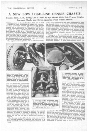
The open propeller shaft employed to convey the drive to the back axle is fitted with a very substantial startype universal joint at each end, the working parts being completely enclosed by neat spherical housings. The back axle is of the Rirkstall forged type with separate ends, bolted on, which carry the Timken• roller hub bearings ; it is of the fully floating type. The wheels are twinned at the rear, and carry straight-sided pneumatic tyres.
The low frame level has been. obtained without abruptly cranking the frame, -the side members being reasonably straight in elevation, but, "or conr.se, are. swept up to clear the back axle. The rear semi-elliptic springs are underslung, springs of a similar type being used at the front.
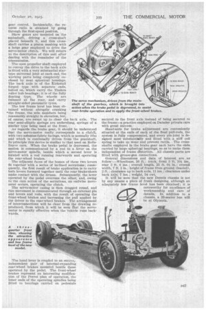
As regards the. brake 'gear, it should be understood that the servo-motor really corresponds to. a cruicli, with two asbestos-fabric facings, which is normally free and which. is continually driven -from the gearshaft. In .principle this device is similar to that used on RollsRoyce -cars. When the brake pedal is depressed, the motion is communicated by a rod to a leveron. the servo-motor spindle, beside which a • second lever is located' with a rod running rearwards and operating the rear-Wheel brakes.
The adjacent faces of the bosses of these two levers fit together with a series of inclined serrations; consequently, the first result of brake application is to carry both levers forward together until the rear brake-Shoes make contact with the drums. Subsequently, the lever operated by the pedal overruns the other, and, owing to the cam action of the serrations, an endwise movement occurs, operating the clutch.
The servo-motor casing is then dragged round, and this Movement is communicated through an external pin and levers and rods, with the result of operating the front-wheel brakes and increasing the .pull applied by the driver to the rear-wheel brakes. The arrangement of interconnections will be clear from the drawing reproduced, from which it will be seen that the servomotor is equally effective when the vehicle runs backwards.
The hand lever is coupled to an entiretj, independent pair of internal-expanding rear-wheel brakes mounted beside those operated by the pedal. The front-wheel brakes represent an interesting modifica, tion of "the Perrot plan of operation, the inner ends of the operating spindles being•fitted to bearings carried on pedestals n4.7
secured to the front axle instead of being secured to the frame—a practice employed on Daimler private cars with great success.
Hand-nuts for brake adjustment are conveniently situated at the ends of each of the final pull-rods, the system is fully compensated, and every pin-joint is designed most substantially and fitted with a stiff coil spring to take up wear and prevent rattle. The crossshafts employed in the brake gear each have the ends carried by large spherical bearings, so as to make them . independent of frame distortion. All chassis parts are fitted with grease-pin connections.
General dimensions and data of interest are ,as follow :—Wheelbase, 16 ft ; track, front 5-ft. 10-4 ins., rear 5 ft. 6 ins. ; overall length, 25 ft. Oi ; overall width, 7 ft. 1 in. ; height of frame from ground (loaded),
2 ft.; clearance up to back axle, 11 ; clearance under back axle, 7 ins. ; weight, 54 cwt.
It will be seen that the new Dennis chassis is not by any means a piece of freak designing, although an adequately low frame level has been obtained ; it is noteworthy for 'excellence of workmanship and care of details. In addition to a chassis, a 33-seater bus will be at Olympia.