


THE REAR AXLE AND FRAME FEATURES.
Page 41
Page 42
Page 43
If you've noticed an error in this article please click here to report it so we can fix it.
The Second of Two Articles in which Present-day Design, Choice of Material and Method of Construction are being Considered.
IN the first of these articles, published in last week's issue of The Commercial Motor, attention was devoted to the engine, the gearbox and the final drive, and modern practice in their design was thoroughly reviewed from the point of view of the needs of the user. The reasons why certain courses and methods in design and construction are adopted by manufacturers were discussed, and the advantages and disadvantages of each to the user or the engineer responsible for the maintenance of a vehicle or a fleet of vehicles were analysed. The discussion is here continued in order that we may consider many other chassis features which are important from the same point of view.
With regard to the surroundings of the rear axle, such as torque tubes, torque rods, radius rods, etc., there seems to be no settlement of the many knotty problems of choice of method that have faced designers. This fact seems to prove that none of the various systems of mounting a rear axle has any pronounced defect, nor any outstanding advantage over the other systems. If this may be taken as an indication of the position, it would seem that the best mounting of the rear axle would be that in which there is the least number of parts to be affected by wear, to cause noise and rattle and to necessitate costly replacements.
In spite of all attacks that have been made on the ordinary semi elliptic spring, as used years ago on carts, it still seems to hold its own against all corners. Even on the pleasure ear such a spring is found to be greatly in favour, as compared with cantilever, transverse, i hreequarter elliptic or quarter-elliptic springs. Now, actually the semi elliptic spring forms a very good means of attaching an axle to a frame. It is unquestionably not a perfect form of spring, but up to now it has hardly a rival. For bus work such springs are found to be improved by the addition of supplementary springs, set wide apart to prevent the rolling action which is a serious trouble when a double-deck body is carried, but for the carrying of ordinary goods such extra springs do not seem to offer any advantage.
In the general construction of frames little alteration seems to have been made for many years, which rather points to the fact that no alteration is required. The provision of vertical struts and a tie-bar, or trussed girder type, is gaining favour. This construction was looked upon some time ago as an admission that the frame proper was insufficient in strength, but one sees it being embodied in many new models.
The frame which is composed of straight side-members is undoubtedly the most simple and easiest to produce, and unless special requirements call for a frame which is bent in any way, bending is better avoided.
The use of rivets in frames is strongly objected to by some of ' the most experienced users of commercial motors, on account,of the trouble they give in the case of an accident which necessitates the stripping and straightening of a frame. Accurately fitted-bright bolts and nuts 'should be used almost throughout. That all units such as engines and gearboxes should be suspended at three points has been recognized for a long time It Is somewhat surprising to see frames , designed in which this point has not been taken into consideration. It should be always borne in mind that commercial motors have at times to go over very uneven ground where a severe twist of the frame must take
place.precaution should be taken to relieve such nits from strains of this kind.
Much has been said lately with regard to the intro. duction of a low loading platform. With the exception of buses that are destined to have bodies with coveredin tops, and the carts for collecting refuse from house to house, it is not certain whether a low platform is an advantage. Most loading docks in goods yards and factories are of the standard height which allows a man to get a sack on his back with the least trouble, and for general goods carrying this is undoubtedly the best
height for the platform of a van. Where a low loading line is essential, one is disposed to make some sacrifice of mechanical efficiency to attain the object; the lovv loading line, however, does not appeal to the writer as offering any great advantage. For the carrying of passengers in a char-k-bancs the low platform may be safer, but it very much decreases the pleasure of travelling, as the passengers cannot see over the hedges. If a double-decked bus is regarded as a sufficiently safe vehicle, where the centre of gravity is undoubtedly high, it may be argued that the charit-bancs of ordinary height is a still safer vehicle and does not call for alteration in the height of the centre of gravity.
Judging front the number of patents which has recently been applied for in connection with improved brakes, it is evident that efforts are being made in the direction of providing something .better than the brake as we know it to-day. The ordinary type in which two shoes are hinged at one point and are expanded at the other end is undoubtedly not scientifically correct, as one end of the n44 shoe must wear away sooner,than the other. In .consequence, many a costly lining has to be discarded, which might, if brought into more correct contact with its drum, have had a much longer life. Apart from this, such brakes have another disadvantage, as they put a very unfair strain on the bearings of the hub.
if recent patents can be taken as a guide, the trend is towards either flexible bands in place of the rigid. shoes, or to shoes that are hinged to each other or articulated. In this class of brake the hinge or joint is. usually allowed to float, so as to be self-assisted to an extent and to relieve the driver from the necessity of making any great effort, for, as matters, stand at present, a driver requires all ,his strength to pull up a heavily laden lorry on a steep decline. Many of the recent patents have been for servoand fluid-operated brakes, and we may expect to see a battle between the various systems. The writer, however, is inclined to think that the system which will survive for general lorry work and for use on the heavier kinds of passenger vehicles will be one that brings the whole length of the lining into even contact with its drum, will be to some extent self-assisted when acting in either direc
tion, and, above all things, will be of simple construe tion.
In a recent number of this journal a very complete article showed some of the most promising of the new , inventions in connection with brakes. With regard to front-wheel brakes as applied to heavy vehicles fitted with solid tyres, the writer is still doubtful as to their ultimate success, owing to the Possibility and dangerous. consequences of a side slip with the front wheels.
Another point which seems to have been somewhat overlookedis that to apply two separate braking systems will take twice the power required to apply one. It is well known that with the ordinary heavy vehicle the strength of the driver is taxed to the utmost in applying one set of brakes to their fullest extent, so it is not easy to see how he is to supply sufficient power to operate two systems unless he receives some assistance such as that derived from a servoor self-assisted mechanism, or from a fluid pressure or vacuum.
With regard to brakes actuated by fluid pressure, the writer is strongly of the opinion that such pressure can only be successfully employed in conjunction with some device that enables the driver to " feel" what pressure he is exerting, as without this " feel" there will always be risks of sideslip.
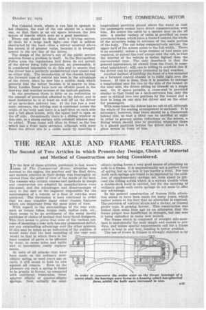
Where vehicles have to work in hilly districts trouble has sometimes been experienced through failures of ball bearings. In many cases the trouble was able to -be traced to too, light a bearing having been fitted in the original design, and the replacement of the original bearing by one of more ample dimensions has been found to be an improvement. The old question as to what is the-best form of journal bearing, whether with filling slot (for assembling the balls in the bearing) or without, is still
unsettled. The
type of bearing eAllo 512ASS in which there is no slot, and in which the outer
ring has a groove which is so arranged that, by slightly expanding it by heat and with a slight pressure, the balls can be forced into position, seems to be increasing in popularity. Our illustration shows an arrangement of a worm drive in which trouble was experienced with certain buses running in an exceptionally. hilly country. Originally this worm was of the sleeve type and was splined to the axle, which passed right through it. Owing to the very severe work these vehicles had to perform, it was found that a slight deflection of the worm shaft took place. The effect of this deflection was to throw the thrust bearing into 811C11 a position that only a few of the balls were taking the load.
The sleeve worm was replaced with one integral with its shaft, special spherical faces were provided as shown in our illustration, the diameter of the balls on the side of the forward drive was increased, and the journal bearings were replaced with the type shown, in which no filling slots are used, the maximum number of balls are employed and a solid cage replaced the original one riveted together. We understand that with this alteration the hearings are now giving every satisfaction, because should the shaft spring at all, the spherical housing for them can move with the shaft and so allow the whole of the balls to continue to bear their share of the load.
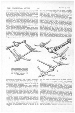
It is essential that all bearings should be provided with some efficient means of retaining the lubricant. An escape of oil may seem an unimportant matter, but in reality it may lead to serious trouble in some cases. If oil be allowed to leak, one does not know to what extent the leakage is reducing the level of oil at the place where it is required, until one day the discovery is made that some important bearing is running dry. In the matter of rear axle bearings, a leak of oil may lead to a brake failure. Thus, looked at from all points, it is best that there should he no leaks. One of the best plans for preventing the leakage of oil from a ball bearing is that shown in our illustration, where a washer of thin, hard brass of a slightly dished form is clamped against the side of a ball bearing.
• The slight friction set up is negligible, and the washer soon wears itself into 'a perfectly oll-tight seal.
Recent experiences with compressed cork washers instead of felt have shown cork to be very useful for oil-retaining, as it does not become impregnated with particles of grit.
The six-wheeler has undoubtedly proved its usefulness for the carrying of heavy loads of goods, but for carrying passengers the writer yet awaits a practical demonstration. Carrying very great numbers of passengers on one vehicle must necessarily increase the number of Stops, and, consequently, cause delays
ThIN WASWela Of•
M:yt, Eel
The use of a brass washer beside a ball bearing to act in retention of the lubricant. and slow progress. This has been found to be the case with tramcars, and was the cause of the trailing cars being abandoned.
With regard to the carrying of goods on six wheels, we have already several very satisfactory models in which the drive is taken by one pair of wheels only. It is, however, unfortunate that the example which has been on show at Wembley for some time, in which four-wheel drive is employed, will not be exhibited at Olympia.
The placing of the driver alongside of his engine fias by now been made familiar to the eye by its adoption on buses, where it is being found to work well. There seems little reason why this form of construction should not find more favour w 11 e r e long and bulky loads have to be carried. The wasting of some 3 ft. of valuable space for a cab seems unnecessary when it can be avoided by adopting the forward position for the driver's seat.
Probably more trouble and expense arise from poor lubrication in the use of commercial vehicles than from any other one cause. Most of the costly renewals can be traced primarily to want of lubrication, or to unsuitable lubricant being used at some time. The use by a driver of grease in places intended for oil to gravitate is a common cause of trouble. The loss of a greasegun, followed by attempts to push grease in with a piece of wood, and forgetting to replace the cap of a Stauffer greaser after filling it often result in costly damage to a vehicle. If one stops and looks at vehicles standing by the kerb, it will be seen that, in most cases, a very high proportion of the greasers are without their caps, or are missing altogether. Flow can mechanism be expected to work satisfactorily under such conditions? The writer strongly advocates the use of oil and the abandonment of-the heavy greases, which cannot gravitate or travel to the places where they are required.
With regard to the lubrication of the engine, this matter is usually well attended to by the designer, who knows full well its importance; hence most engines are turned out with a system which can be relied upon, so long as they are kept supplied with the necessary amount of lubricant ; neglect of this point, however, cannot be helped or prevented by the designer. An efficient tell-tale to show that there is a sufficient supply of oil, and that it is circulating properly, is essential ; such an indicator should be visible by night as well as day. The neglect of this latter point has been responsible for many a costly overhaul.
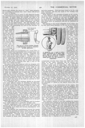
The ordinary method of one firm making the chassis and another firm making the jack may be all right from an economical point a view, but there seems no reason why such firms should not work with some regard for each other's designs. The plan suggested in our illustration, where a dovetailed groove is provided for the reception of the head of the jack, might be carried out with advantage. In many eases where a tie-bar is fitted under the rear axle and where the front axle slopes under the spring clip, there is considerable difficulty in finding a convenient place for the jack to operate, and accidents due to slipping are not unknown, A platform for a jack is absolutely essential, as it often happens that no place is available for the head of a jack. A dovetailed groove for the purpose is suggested.