


NOVEL FEATURES OF A RIGID SIX-WHEELER.
Page 32
Page 33
If you've noticed an error in this article please click here to report it so we can fix it.
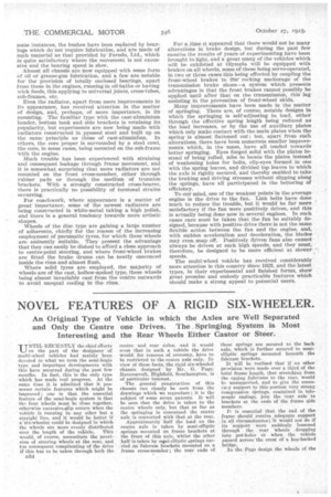
An Original Type of Vehicle in which the Axles are Well Separated and Only the Centre one Drives. The Springing System is Most Interesting and the Rear Wheels Either Castor or Steer.
UNTIL RECENTLY the chief efforts on the part of the designers of multi-wheel vehicles had mainly been devoted to what we term the semi-bogie type and important developments with this have occurred during the past few months. In fact, this is the only type which has made real progress. At the same time it is admitted that it possesses certain features which might be improved ; one is that the essential feature of the semi-bogie system is that the four wheels must be close together, otherwise excessivesslip occurs when the vehicle is running in any other but a straight line, and it would be hotter if a Six-wheeler could be designed in which the wheels are more evenly distributed over the length of the vehicle. This would, of course, necessitate the provision of steering wheels at the rear, and the consequent complicating of the drive if this has to be taken through both the
D34
centre and rear axles, and it would scam that in such a vehicle the drive would for reasons Of economy, have to be restricted to the centre axle only. In view of these facts, the rigid six-wheeled chassis designed by Mr. G. Page, Ra,vonscroft, Highfield, Southampton, is of particular interest.
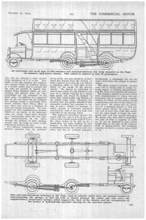
The general construction of this chassis can clearly be seen from the drawings which we reproduce ; it is the subject of some seven patents. It will be seen that the drive is taken to the centre wheels only, but that so far as the springing is concerned the centre axle is connected with that at the rear.
Approximately half the load on the centre axle is taken by semi-elliptic springs mounted on frame brackets at the front of this axle, whilst the other half is taken by serni-elliptic springs carried on fulcrum brackets mounted on a frame cross-member; the rear ends of
these springs are secured to the back axle, which is further secured to semielliptic springs mounted beneath the fulcrum brackets.
It will be realized that if no other pravision were made over a third of the total frame length, that stretching from the spring .fulcrums to the rear, would b3 unsupported, and to give the neces;my support to this portion very strong compression springs, contained in telescopic casings, join the rear axle to brackets at the ends of the frame side members.
It is essential that the end of the frame should receive adequate support . in all circumstances ; it would not do if its 6npp6rt were suddenly lessened through the roar wheels dropping into pot-holes or when the vehicle passed across the crest of a hog-backed bridge.
In the Page design the wheels of the
rear axle are allowed a total up-anddown movement of 2 ft. 6 ins. Normally, if the axle dropped, the compression springs would be rendered useless to a certain extent, and to prevent this the ends are carried on special camshaped frame brackets which, by compressing the springs from the rear, compensate for the extension at the front ends. In addition, it is apparent that as the axle rises and the compression springs resume a practically horizontal position, their lifting effect is lost ; there may even be a tendency to force the chassis downwards. To compensate for this, supplementary springs, which are not shown in the drawings, • come into action, these being situated m a cross-member above the rear axle. The interconnection of the axles, through the medium of their springs, ensures that the loads are more evenly distributed between the two.
For ordinary commercial service,. the inventor proposes that the stub-axle pivots of the rear axle should be pitched about five degrees from the vertical, in such a manner as to give the rear wheels a oastoring effect so that they would follow in the tracks of the driving wheels. We should be interested to observe the action of such wheels in the case of a vehicle running at a fairly high speed, and would -be inclined to think that wheel-wobble and tailwag of the vehicle might occur. However, the inventor does not confine himself to this automatic method, but proposes, in the case of heavy vehicles or tractors, to utilize vacuum or hydraulic cylinders connected by rods to steering links and controlled by the steering wheel.
The suggested wheelbase between the centre and rear axle is 8 ft. 6 ins., and with a total overall length of 29 ft. 6 ins. Mr. Page claims to be able to fit a double-deck bus body holding 78 passengers. In this bus body the entrance is situated between the centre and rear axles, and has an enclosed staircase. Incidentally, a detachable top for the upper deck forms the subject of another patent.
The whole design is unusual—we may even call it daring—but it would certainly appear to possess potentialities. and Mr. Page is an experienced engineer.
The designer desires to get into touch with manufacturers or others who are interested, and we suggest that anybody wishing to follow up the matter should communicate with him at the address we have given. He claims that the alteration of a standard chassis to this shewheel system should not exceed a factory cost of more than MO, this including the extra length of frame, the additional axle and the special springing. He states, also, that with a pantechnicon type of body a capacity of 1,400 cu. ft. can be obtained in less overall length than in the case of the ordinary form of tractor-trailer, the maxinnim capacity of which is usually about 1,100 cu. ft.