


Patents Completed.
Page 20
If you've noticed an error in this article please click here to report it so we can fix it.
Complete specifications of the following patents will be sent to any address in the United Kingdom upon receipt of eightpence per copy at the Sale Branch, Patent Office, Holborn, W.C.
CARBURETTER. — Parker. — No. 17,286/1909, dated 24th February, 1910. —In this carburetter, air under pressure is led into an annular chamber surrounding the fuel pipe and passes thence by helical passages to a chamber just above the fuel jet. Fuel is sucked in by the air, and the mixture passes from this chamber by a fine jet into a heater which is constructed like surface condenser. This heater consists of a large number of fine tubes arranged between tubeplates in a chamber through which the exhaust circulates. It is stated that this construction prevents back-firing, and that the cooling of the exhaust tends to make it more 8i1ent than it would be otherwise.
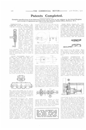
s.:RANK CH AM BERS.—Martin and Another.—No. 24,096. dated 20th October, 1909.—This invention relates to crank chambers for steam and gas engines, particularly to those for internalcombustion enginee with vertical cylinders. The erankashamber is constructed in three essential pieces: one forming the top. and adapted to carry the cylinders, another forming the bottom part. and the third part, a plate carrying the bearings of the crankshaft and held between trie upper and lower portions. It is clamped at the sides to the flanges of the upper and lower portions of the crank-eham
her. and in the middle may be tied or supported by bolts employed to hold the chamber together. When half-time camshafts are used, these work in bearings supported en the plate ; an example is shown in the sectional view.
TRACTOR.—Crompton.—No. 22,416. dated 1st October, 19C9.—This invention relates to road locomotives or tractors, and it has for its object improvements in the construction of such vehicles whereby a high hauling efficiency may he obtained. It is therefire necessary to use large driving wheels, and this design is intended to obviate the disadvantages censequent on the use of such wheels. The chassis of the tractor is suspended from the axle of the driving wheels by means of ordinary springs snspended in hangers from the ends of the axle. In order to constrain the chassis from any lateral movement without imparting other constraint to it, a guide plate is centrallyfixed on the rear axle and extende downward to embrace a central guide lock pivotally mounted on the chassis. This arrangement permits of angular, longitudinal, and vertical move
meat of the ehussis rela ive ti the rear axle, but it entirely prevents any lateral movement. The transmission and roping gear are both mounted on a self-contained bed-plate, which is preferably ( f cast steel and of channel section in order to obtain very great rigidity. This bedplate is rectangular and is bolted to the
chassis in such n IllatTher that it constitutes ea integral part, serving as a stiffening component. By thus supporting the transmission and the roping gears. the strains transmiltsd thereby are distributed over a considerable area of the chassis instead of being concentrated upon it pair of ha iii as is usually the case. The pe‘ver is transmitted from the engine shaft by it worm gear to the countershaft. A worm Wheel is mounted
upon a sleeve which is keyed to a hollow .
shaft that is capable of longitudinal inei-ement. This nmvement is in ilizsd for did-chime the roping gear or the propelling gear to the engine. The propelling gear consists of the ordinary piniontype differential, which drives oa to the
central solid shah. Pinions or rhain
wheels, fixed at the outfr ends, 'LUAUS/la the drive to the road wheels. The rope drum is mounted in the middle on a second hollow sleeve, and can be coupled directly to the inner hollow sleeve.
LEAD SEAL.—Treude.--No. 7,193, dated 22nd March, 1910.—This specification describes a sealing device which consists of two halves which are hinged together. One part has a high projectiiig rim which is folded over and encloses the other part when the seal is closed. The connecting hinge is made as short as possible, so that it is folded over with the rim. The central portions of the two elites are dished, and the projections
thus 'formed secure the strings. These strings form an elastic support, so that an impression Call be printed on either or both of the dished portions of the discs.
MAGNETO DISTRIBUTOR ATTACHMENT.— De Dion-Bouton.— No. 10,780/1910, date claimed under Convention 25th 11-lay, 1909.—The object of this invention is to attach the cover of a secondary-current distributor to the frame of a magneto, in such a way that, while it is securely held in place, it may at. the same time be easily removed. The distributor is so shaped as to form, with the frame, a box enclosing the toothed conducting ring which carries the current. to the distributor cover, and which is mounted on an insulating disc also toothed. This disc is carried on a hollow shaft working in ball bearings in the
jeurnal fixed on the frame of the magneto. In the distributor cover, is fixed a plug which is slotted and cut away at the left-hand end as shown iii the drawing, so that there is a recessed portion at right. angles to the slot. A rod has a cross pin fixed in the end, and this pin is held into the slot by a spring acting on a disc at the other end of the rod, which extends I hrough the hollow shaft in suitable beariege on the frame of the magneto. To detach the cover, it is only necessary to give this rod a quarter turn, when the pin will be pulled in by the cam face and ceme intn line with the slot in the plug. se that it can be withdrawn. The distributor cover is then removed without any forther deteehments' being necessary,