


Stevens' s Latest Petrol-Electric Bus Chassis.
Page 13
Page 14
If you've noticed an error in this article please click here to report it so we can fix it.
A considerable amount of success has been obtained with the HanfordStevens system of petrol-electric transmission as applied to a motorbus in the service of Thomas Tilling, Ltd., which vehicle has now travelled more than 83,000 miles in London public service. In that vehicle, as will be remembered from descriptions given in our issues of the 16th January, 1908, and the 16th December, 1909, the final drive to the back wheels is by means of two electric motors which are direct coupled to worm gears on the driving wheels. This system of drive was jointly patented by Mr. Percy Frost Smith, chief engineer to Thomas Tilling, Lid., Mr. Flank Brown, of Huddersfield, and Mr. W. A. Stevens, the inventor of the electrical system. In addition to Tilling's machine, Hallford-Stevens vehicles are in use by the War Department, the Brighton, Hove and Preston United Omnibus Co., Ltd., and on the Loughborough omnibus service.
lii Mr. Stevens's latest application of his system only one continuous-current dynamo and one motor are employed. The dynamo is coupled to an engine (which has four cylinders each 10(1 mm. in dinmeter, mai, with a piston stroke of 1.50 nuts, gives 24.85 lep., according to the It .A.C. rating), by means of a flexible coupling. The dynamo is of the shunt-woued interpolar type, designed to run sparkles.sly with any load or at any speed. It supplies electrical energy to a series-wound electric motor which is direct-coupled to a Dennis worm-driven live axle. When working at its full load, the output of the dynamo is 22 kilowatts. The motor is one of the four-pole enelosed type, similar to those used for tramway service, and it is of ample size to deal with the w hole output of the dynamo.
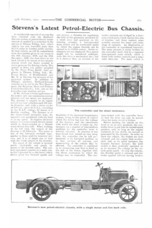
The speed of the vehicle is secured partly electrically and partly by means of the throttle valve. The control equipment consists of a main controller (operated try a side lever) which derive gives two forward speeds and one reverse, a rheostat for regulating the field of the generator (actuated by a small lever and quadrant on the steering column), a foot-operated main switch and an accelerator pedal by which the engine throttle can be opened to its fullest extent. Series resistances are not employed. Two speeds might not be considered sufficient, were the drive a mechanical one; but it is claimed that, on account of the flexibility of the electrical transmission system, owing to the power of control which the driver has over the voltage of the dynamo, and the smoothness with which the drive is taken up, the necessity for a number of intermediate positions for the controller lever is entirely obviated. In practice it has been found that, except on very steep hills, the controller can be left pe-manently in its top-speed position, as in that, position all starting and mameuvring of the vehicle may be effected. The controller is contained in an aluminium case that is fixed on the side of the frame, together with the shunt resistanees by which the voltnge may be controlled. The con• troller contacts are bridged by a fouraria switch piece which carries two setsof brushes, :Ind these contact arms suitably connect the inner and outerrings of contacts. An illustration ot the controller is reproduced herewith._ The main current is never broken on: the controller itself, but by a separate: foot-operated main switch, which fitted with carbon contacts and a magnetic blow-out. The main switch is; inter-locked with the controller leveeso that the lever ran only be moved when the main circuit is broken.
Before starting the vehicle on the • level or on an easy gradient, the controller lever is put iuto its second-speech. position, and, so long as the engine continues to run slowly, no current i&. generatedby the dynamo. In order to.> start tile vehicle, the brakes are first released, and the engine then accelerated, and, as its speed increases the' dynamo becomes excited; the field switch is then gradually operated sce as to increase the voltage as the vehicle gains speed. To stop the vehiclem the throttle pedal is released and •thes brake applied without having broken:
the main current. It, should be observed that the accelerator and main switch pedals are both operated by the driver's right foot, so that he cannot depress both of them at the same tune. It should be noted that, although the principal control is by means of the throttle pedal, attention must also be paid by the driver to the manipulation of the field switch, but a very small amount of practice will enable him to determine the best position of the field switch for different circumstances of load and speed. The manner in which it is handled is not unlike that of the ignition lever of a petrol engine; it should be retarded when, the engine is running slowly under a heavy load, and advanced for .high engine speeds. The transmission is purely electrical, there being no direct coupling between the dynamo and motor shafts when the vehicle is running at top speed. In the top-speed position, by the operation of the controller, a shunt is in serted in parallel with the motor fields, and this shunt may be varied to suit local conditions: the less resistance in the shunt the greater ratio of motor speed to engine speed, and vice versa.
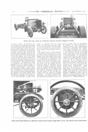
The model which we here illustrate is intended for public service in Central India, and two machines have been shipped from the London docks ; each will be fitted with a char-h-banes body to accommodate 40 passengers. The weight of the chassis is 2 tons 17 cwt., too heavy, of course, for London omnibus service, but the builder does not anticipate that any difficulty will he found in building a chassis to comply with the weight requirements of the police regulations, as it is argued that an electrical equipment giving only half the power of the one here described would be ample for London conditions. Stevens's petrol-electric omnibuses of a rather smaller type than that here described are now run
ning in public service at the Hague. 'In addition to their suitability foi shooting brakes, light chars-i-bands. and private omnibuses, these vehicle: have many advantages for military work, chiefly owing to their carrying a self-contained electric generating plant, which may be used for working a large searchlight. For the past twc years. Hallford-Stevens petrol-electric vehicles have been jointly manufactured by J. and E. Hall, Ltd. of Dartford, and W. A. Stevens, Ltd., of Maidstone, under the patents of Mr. Stevens and the S.B. and S. Syndicate. Owing to the great increase in the motor-vehicle department (gear. driven)of the business of J. and E. Hall, Ltd., it has mutually been arranged that the whole of the petrolelectric work shall be carried out at Stevens's Maidstone works, and the system in future will be known anE Stevens petrol-electric chassis—not, m formerly, the " Hallford-Stevens."