


A Novel Crankshaft Layout T HE high torque developed by modern
Page 60
If you've noticed an error in this article please click here to report it so we can fix it.
engines gives rise to many problems in connection with torsional stresses in the cranshaft, and in this regard a novel scheme is proposed in patent No. 442,694 by the Birmingham Aluminium Casting (1903), Co., Ltd., of Dartmouth Road, Smethwick, near Birmingham, and P. Pritchard.
The scheme -provides for a layshaft running parallel with the crankshaft, and . fitted with gears . meshing with gears on the crankshaft main bearings. In the accompanying drawing, which shows a six-cylindered V-type engine, the layshaft (8) forms the power output member, receiving the drive from gears 4 and 1, the latter being formed between the rollers (2) of the main bearings.
By this means, it is stated, the torsional load at any point on the crankshaft is limited to that imparted by the nearest connecting rod. This state' ment, however, whilst probably true of the main torque, appears _to ignore the fluctuations transmitted to the flywheel.
Obtaining a High-speed Injection.
A C:ORDING to W. Koster, 2, Solms
strasse, Frankfort-on-Main, and A. Dussmann, 38, Rossmarkt, Aschaffenburg, Germany, satisfactory operation of an oil engine demands that the injection be as rapid as possible. The cam-driven types of pump already on the market achieve this up to the mechanical limits of cam action, but even this is stated to be insufficient.
In patent No. 441,872 the above inventors disclose an injector in which the operating medium is compressed an in combination with a 'novel plunger action. In the drawing, compressed air arrives via the conduit. (4), passes an on-or-off valve (5) and meets a rotary distributing valve, (8). This valve is the equivalent of the camshaft, and rotates in timed relationship with the 13443 engine. When air is admitted to the pump-operating piston (2) it commences to rise, but in consequence of the large size of the fuel suction port (1) there is a considerable length of idle movement before injection commences. It is claimed that during this movement the plunger and its piston attain a high velocity, and thus the injection is started by impact from a moving mass.
Keeping the Exhaust Valves Cool.
TIlAT the temperature of the exhaust valves is the limiting factor in the choice of a compression ratio is the statement made in patent No. 441,458, which describes a method of cooling the exhaust valves by means of the incoming gases. The inventor is R. P. Lemasson, 6, Rue Frementine, Paris,
The accompanying drawing shows one of several schemes, the underlying principle of all of them being the interposition of some form of deflector (1) in the path of the incoming gases, so that they are forced to impinge on the head of the exhaust valve (2). The inventor states that the scheme possesses the additional advantage of Control of injection-pump Outfit.
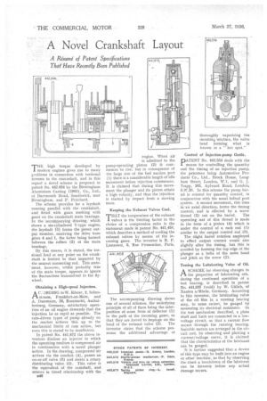
PATENT No. 442,554 deals with the means for controlling the quantity and the timing of an injection pump, the patentees being Automotive Products Co., Ltd., Brock House, Langham Street, London, W.1, and G. J. Trapp, 105, Aylward Road, London, S.W.20. In this scheme the pump barrel is rotated for quantity control, in conjunction With the usual helical port system. A second movement, this time in an axial direction, forms the timing control, and is effected by a screw
thread (2) cut on the barrel. The operating nut of this thread is made in the form of a pinion (4) which is under the control of a rack rod (1) similar to the output control rod (3).
The slight barrel rotation employed to effect output control would also slightly alter the timing, but this is avoided by forming the top edge of the plunger as a helix of the same hand and pitch as the screw (2).
Testing the Lubricating Value of Oil.
ASCHEME for observing changes in the properties of lubricating oils, during the continued operation of a test bearing, is described in patent No. 441,837 (void) by W. Giilich, of Xanten a/Rhein, Germany. According to this inventor,, the lubricating value of the oil film in a running bearing may, to some extent, be gauged by measuring its electrical resistance. In the test mechanism described, a plain shaft and bush are connected in a lowvoltage circuit, so that a current flow occurs through the running bearing. Suitable meters are arranged in the circuit and, by observing and plotting a current/voltage curve, it is claimed that the characteristics of the lubricant can be gauged.
It is further suggested that a device of this type may he built into an engine or other machine, so that by observing the chart a breakdown of the lubricant can be foreseen before any actual damage occurs.