 1
1 2
2 3
3 4
4 5
5 6
6 7
7 8
8 9
9 10
10 11
11 12
12 13
13 14
14 15
15 16
16 17
17 18
18 19
19 20
20 21
21 22
22 23
23 24
24 25
25 26
26 27
27 28
28 29
29 30
30 31
31 32
32 33
33 34
34 35
35 36
36 37
37 38
38 39
39 40
40 41
41 42
42 43
43 44
44 45
45 46
46 47
47 48
48 49
49 50
50 51
51 52
52 53
53 54
54 55
55 56
56 57
57 58
58 59
59 60
60 61
61 62
62 63
63 64
64 65
65 66
66 67
67 68
68 69
69 70
70 71
71 72
72 73
73 74
74 75
75 76
76 77
77 78
78 79
79 80
80 81
81 82
82 83
83 84
84 85
85 86
86 87
87 88
88 89
89 90
90 91
91 92
92 93
93 94
94 95
95 96
96 97
97 98
98 99
99 100
100 101
101 102
102 103
103 104
104 105
105 106
106 107
107 108
108 109
109 110
110 111
111 112
112 113
113 114
114 115
115 116
116 117
117 118
118 119
119 120
120 121
121 122
122 123
123 124
124 125
125 126
126 127
127 128
128 129
129 130
130 131
131 132
132 133
133 134
134 135
135 136
136 137
137 138
138 139
139 140
140 141
141 142
142 143
143 144
144 145
145 146
146 147
147 148
148 149
149 150
150 151
151 152
152 153
153 154
154 155
155 156
156 157
157 158
158 159
159 160
160 161
161 162
162 163
163 164
164 165
165 166
166 167
167 168
168 169
169 170
170 171
171 172
172 173
173 174
174 175
175 176
176 177
177 178
178 179
179 180
180 181
181 182
182 183
183 184
184 185
185 186
186 187
187 188
188 GEAR REDUCTION IN SERIES.
Page 138
If you've noticed an error in this article please click here to report it so we can fix it.
Resume of Recently Published Patent Specifeations. A
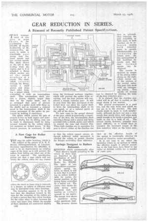
Tr H E arrangement of two g,ears in series shuwn inthe specification No. 285,558, Of Saville Rushworth, of St. Annes-on-Sea, appears. to make a practieable gear giving four forward speeds and two reverse speeds. The shaft shown on the left is that leading from the engine, and to it is attached a flange which carries one of the conical members of a clutch. The shaft, which. extends through the flange, carries a small pinion and stops ahort after forming a spigot which
cantralizes it with an intermediate shaft. This intermediate shaft car ries a pinion, slightly larger than that on the engine shaft, and is so arranged that pairs of pinions
mounted in a spider mesh with those on the shafts and so transmit a reduced speed to the intermediate shaft if the rotary movement a the spider be prevented by holding it stationary.
The spider which carries the pair of pinions is free on both engine and inter mediate shafts, but its sliding cone can be made to disconnect itself by being pressed inwards by the rollers which
are' mounted on forked levers. If this inward pressure be continued, it will bring the frictional surfaces together, which will prevent the spider from revolving, and the four pinions will constitute a simple reducing gear. It will be seen from this that movement of the forked lever can allow the engine shaft to drive the intermediate shaft at its own speed, or at a reduced speed, at the will of the driver.
We now come to the second element of the gear, which is practically a repetition of the first, the intermediate shaft carrying a flange and a pinion and being provided with a clutch, spider and rollers to control the cone and friction disc. When both clutches are in operation the gear is direct ; either of the clutches can then be released, thus reducing the gear according to their ratio, or both clutches can be released, causing both reduction gears to operate simultaneously, a o producing the lowest gear. By this arrangement it Will doubtless be clearly seen that four forward speeds can be obtained.
The reverse is obtained by means of the sliding collar shown on the right, which moves one of the pinions.of the second reduction gear into mesh with an interpos ing pinion. Two speeds of reverse can la obtained by altering the ratio of the first reduction gear.
It is claimed that the clutches provided will do all that is needed, so the usual clutch is not wanted.
The general arrangement is a good one, and the only weak spot which we can see is in the clutches. The first clutch might be made to work satisfactorily, although we have not seen a cone clutch that would drive well when made small enough to be inside a gearbox, and made to run in a bath of oil. The second clutch, however, presents even snore difficulty,. as it would have to transmit the increased torque of the first reduction when on the lower gear.