 1
1 2
2 3
3 4
4 5
5 6
6 7
7 8
8 9
9 10
10 11
11 12
12 13
13 14
14 15
15 16
16 17
17 18
18 19
19 20
20 21
21 22
22 23
23 24
24 25
25 26
26 27
27 28
28 29
29 30
30 31
31 32
32 33
33 34
34 35
35 36
36 37
37 38
38 39
39 40
40 41
41 42
42 43
43 44
44 45
45 46
46 47
47 48
48 49
49 50
50 51
51 52
52 53
53 54
54 55
55 56
56 57
57 58
58 59
59 60
60 61
61 62
62 63
63 64
64 65
65 66
66 67
67 68
68 69
69 70
70 71
71 72
72 73
73 74
74 75
75 76
76 77
77 78
78 79
79 80
80 81
81 82
82 83
83 84
84 85
85 86
86 87
87 88
88 89
89 90
90 91
91 92
92 93
93 94
94 95
95 96
96 97
97 98
98 99
99 100
100 101
101 102
102 103
103 104
104 105
105 106
106 107
107 108
108 109
109 110
110 111
111 112
112 113
113 114
114 115
115 116
116 117
117 118
118 119
119 120
120 121
121 122
122 123
123 124
124 125
125 126
126 127
127 128
128 129
129 130
130 131
131 132
132 133
133 134
134 135
135 136
136 137
137 138
138 139
139 140
140 141
141 142
142 143
143 144
144 145
145 146
146 147
147 148
148 149
149 150
150 151
151 152
152 153
153 154
154 155
155 156
156 157
157 158
158 159
159 160
160 161
161 162
162 163
163 164
164 165
165 166
166 167
167 168
168 169
169 170
170 171
171 172
172 173
173 174
174 175
175 176
176 177
177 178
178 179
179 180
180 181
181 182
182 183
183 184
184 185
185 186
186 187
187 188
188 A New Cage for Roller Bearings.
Page 138
If you've noticed an error in this article please click here to report it so we can fix it.
THE cage for roller beatings, which is
the subject of the patent of S. K. F. Norma Aktiengesellschaft, of Caustatt, Germany (specification No. 280,942), is said to be an improvement on existing cages of the kind, as it will prevent the rollers from falling out when one of the races is removed. The specification points out that a cage which will not retain the rollers, when for any reason either the outer or inner ring is removed, Is a danger, as rollers of different sizes may be assembled from other bearings.
The invention appears to lie in the fact that the chambers formed in the cage for the reception of the rollers are of such a nature that they allow freedom for the roller when in place between the outer and inner ring, whilst the mouths of these chambers are contracted slightly so that the rollers cannot escape, although sufficient radial movement is allowed the rollers to permit clearing the flanges controlling them sideways.
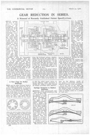
Springs Designed to Reduce Rebound.
SPRINGS which automatically .alter their effective length according to the extent of their load, are described in the specification of Adolf W. H. Kiimpfer, of Berlin, No. 278,322. The upper of our views shows a quarterelliptic spring unladen, in which it will be seen that it is bearin on rollers farthest fuom its centre, the lateral position of the spring being controlled by a radius rod. The centre view shows the same spring under maximum load and bearing on rollers nearest to its centre. The lowest view shows a cantilever spring under maximum load.
The inventor claims that as the effective length of the spring is continually Altering its period of vibration .varies accordingly.
It is not easy to see where the invention comes in, as springs in which theeffective length is altered according to the load have been fitted to one make of British vehicle for a number of years past.