 1
1 2
2 3
3 4
4 5
5 6
6 7
7 8
8 9
9 10
10 11
11 12
12 13
13 14
14 15
15 16
16 17
17 18
18 19
19 20
20 21
21 22
22 23
23 24
24 25
25 26
26 27
27 28
28 29
29 30
30 31
31 32
32 33
33 34
34 35
35 36
36 37
37 38
38 39
39 40
40 41
41 42
42 43
43 44
44 45
45 46
46 47
47 48
48 49
49 50
50 51
51 52
52 53
53 54
54 55
55 56
56 57
57 58
58 59
59 60
60 61
61 62
62 63
63 64
64 65
65 66
66 67
67 68
68 69
69 70
70 71
71 72
72 73
73 74
74 75
75 76
76 77
77 78
78 79
79 80
80 81
81 82
82 83
83 84
84 85
85 86
86 87
87 88
88 89
89 90
90 91
91 92
92 93
93 94
94 95
95 96
96 97
97 98
98 99
99 100
100 101
101 102
102 103
103 104
104 105
105 106
106 107
107 108
108 109
109 110
110 111
111 112
112 113
113 114
114 115
115 116
116 117
117 118
118 119
119 120
120 121
121 122
122 123
123 124
124 125
125 126
126 127
127 128
128 129
129 130
130 131
131 132
132 133
133 134
134 135
135 136
136 137
137 138
138 139
139 140
140 141
141 142
142 143
143 144
144 145
145 146
146 147
147 148
148 149
149 150
150 151
151 152
152 road and workshop by Handyman
Page 108
If you've noticed an error in this article please click here to report it so we can fix it.
Hazard warning lights
THE enforced immobility of a large vehicle even for a few minutes can create a hazard that it may be impossible immediately to do anything about apart from advertising its presence in as blatant a way as possible. Hazard warning lights have taken on in a big way, and the more the better. The system is a relatively simple one and fitting it to a vehicle indicates that the operator is safety conscious.
In the case of a smaller vehicle he is at least conscious of his own safety, which is better than nothing. And it is worth noting that switching on the lights when the engine has cut-out but the vehicle is still moving is an ignore-at-your-peril indication that the driver is in trouble. This can be particularly useful on a motorway or in fast-moving traffic on any type of road.
As is now well known a hazard-warninglight system automatically causes all the direction indicator lights of the vehicle on each side to flash in unison when it is switched on. Known as the HW2 the Lucas electric hazard warning device is, for example, easy to install and will flash up to a total of 12 24V 24W bulbs. A black metal case houses an electronic flasher unit, a relay, a multi-contact switch and an in-line 35 amp fuse. It is operated by a rocker switch, and a flashing red warning light at the side of the box indicates that the system is in use.
The box can be mounted in any con
venient position in the cab in which the warning light is clearly visible. It is necessary to drill four holes at fixing centres of 80mm x 88mm, the overall dimensions of the box being 140mm x 102mm x 40mm.
Pre-wired for connection into an existing circuit, the device has cable-end terminals of the snap-connection-bullet type. It is "polarity conscious" and while it is supplied ready for negative-earth applications it can be adapted to a positive-earth circuit by interchanging the connections on the base of the flasher unit. When it is connected to an insulated return circuit it is necessary to check the polarity of the return system (which is normally negative) and to wire up accordingly.
The feed to the device is taken from the battery either direct or by looping it in at an appropriate point in the wiring circuit. It will, therefore, operate whether or not the ignition /auxiliary switch is "on" or "off". When it is in the "on" position, the flasher unit of the normal indicator system is isolated from the circuit while the flashing indicator lights are operating, including the lights in the trailer, if there is one.
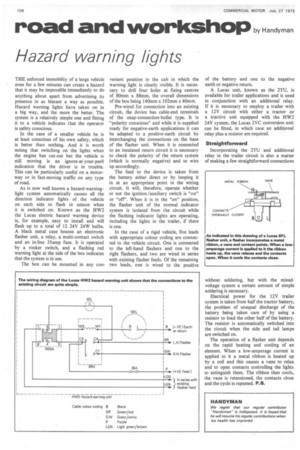
In the case of a rigid vehicle, five leads with appropriate colour coding are connected to the vehicle circuit. One is connected to the left-hand flashers and one to the right flashers, and two are wired in series with existing flasher feeds. Of the remaining two leads, one is wired to the positive of the battery and one to the negative earth or negative return.
A Lucas unit, known as the 2TU, is available for trailer applications and is used in conjunction with an additional relay. If it is necessary to employ a trailer with a 12V circuit with either a tractor or a tractive unit equipped with the HW2 24V system, the Lucas 2VC conversion unit can be fitted, in which case an additional relay plus a resistor are required.
Straightforward Incorporating the 2TU and additional relay in the trailer circuit is also a matter of making a few straightforward connections without soldering, but with the mixedvoltage system a certain amount of simple soldering is necessary.
Electrical power for the 12V trailer system is taken from half the tractor battery, the problem of unequal discharge of the battery being taken care of by using a resistor to load the other half of the battery. The resistor is automatically switched into the circuit when the side and tail lamps are switched on.
The operation of a flasher unit depends on the rapid heating and cooling of an element. When a low-amperage current is applied to it a metal ribbon is heated up by a coil and this causes a vane to relax and to open contacts controlling the lights to extinguish them. The ribbon then cools, the vane is retensioned, the contacts close and the cycle is repeated. P. B.