


A Sealed Self-adjusting Tappet
Page 62
If you've noticed an error in this article please click here to report it so we can fix it.
SELF-ADJUST1NG tappets of the hydraulic type usually require a continuous supply of fluid, such as
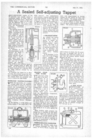
engine-oil, for their action. Patent No. 654,046, shows a tappet of this type, with the difference that it ic a completely sealed unit. The patent comes from the Weatherhead Company, Cleveland, Ohio, U.S.A.
' The dewing shows the tappet in place on an engine. It consists of the usual hydraulic piston and cylinder (1 and 2), but the two are united at the upper end by a bonded rubber bush (3) which, although forming a complete seal, will nevertheless permit the slight relative movement required for the action of the device.
It functions in the following manner; on the upstroke, the liquid is trapped except for a minute leak-port (4) connecting space 5 with a small space ab9ve the piston. Consequently the unit acts as a solid member, the leak-port being unable to pass sufficient liquid in a single working stroke to affect the length. On the downstroke, the liquid is rapidly returned via a one-way valve (6) under press ire created by an air-bag (7); If, however, the tappet be in effect too long, the pressure across the leak port is continuous instead of cyclic, and the trapped fluid can gradually leak away to restore the right length.
HYDRAULIC MASTER-CYLINDER .\
WHEN the -cup-washer of a masterVY cylinder slides over the replenishment port there is usually no pressure present, but circumstances can arise, particularly with a "hold-on" schexe, when this is not so. Then, the pressure may force up a "pimple" on the sealing washer which leads to its tearing and subsequent destruction. To prevent any possibility of this occurring is the aim of an improved master-cylinder shown in patent No. 654,528, by the Hydraulic Brake Company, Detroit, Michigan, U.S.A.
In the drawing, 1 is the piston and sealing washer, 2 the outlet and 3 the fluid reservoir. .The replenishment port contains a tipping valve (4), shown in its open position, in which liquid can reach the working space. The, valve is tipped at the end of the stroke by a rim (5) moving with the piston. When the piston is forced to the right, the valve assumes a square position and seals off the reservoir by a combination of spring force and loading from the working pressure.
A DRAWBAR HOOK
ALIGHT . but strong drawbar hook is shown in patent No. 654,556, by E. Wirz, Uetikon-am-See, Switzerland. The hook is in the form of a ring, with an opening portion to admit the drawbar; this avoids loading the hook with heavy bending stresses.
In the drawing, 1 is the hook and 2 the swinging closure member, The latter is provided with a cup (3) which embraces the top of the hook when in the closed position. A spring-loaded stirrup (4) imparts a snap action to the movement, and a screw 15) is tightened to lock the device. As a further security measure, a pin_ (not shown) can be slid through the assembly.
SEALING GEARTYPE PUMPS
THEgear-type pump as used in the lubricating 'system of an
engine is open to the objection that sealing of the gears in an end wise direction is difficult without heavily loading them. A means for forming a seal is shown in patent No. 654,660, which comes from the Borg-Warner Chicago, Illinois, U.S.A.
The drawing shows a section of the proposed pump taken through the inlet and discharge ports, which accounts for the large spaces 1 and 2. The gears (3) run in bushes (4 and 5), the latter one being the chief pointof interest. This contains a piston-like sliding member (6) which is normally loaded by a light spring so as to press against the gear.
When working under pressure, the spring force is amplified by the action of the off which can reach the piston via port 7. The spring chamber is open to the pressure on the suction side via port 8 so that the effective end-load on the gear is proportional to the developed pumping pressure.
VEHICLE-HEATING RADIATOR
PATENT No. 654,220, comes from Clayton Dewandre Co., Ltd., and others_ of Titanic Works. Lincoln. and
deals with improvements in heating systems for the interior of buses and other vehicles. The scheme utilizes the heat from the engine-cooling water.
A special radiator is used, divided into two parts, called primary and secondary. The primary section is small, and is always in circuit, but the secondary part is brought into use by a thermostat only when the conditions are such that the primary section cannot dissipate the heat.
The drawing shows the radiator, in which 1 is the primary and 2 the secondary sections the pair being separated by a partition (3). The thermostatic valve for bringing the secondary into action is shown at 4. At the rear of the primary part is an air-collecting chamber (5) from which leads a duct (6) to the interior of the vehicle, with or without an electric fan to assist the air-flow. Inside the vehicle, the duct is provided with its outlets one under each window; this serves to de-mist the glass before the air reaches the main body space.
A NEW ALLOY
PARTICULARS of an aluminiumbronze containing copper, nickel, iron, manganese and beryllium, are given in patent No. 654,970, taken out by V. Moyle, Hampton Wick. The beryllium is the novelty, and is said to result in a considerable increase in strength, especially in the direction of proof-stress. An example mentioned gave on test an ultimate strength of 42.7 tons per sq. in.