


Bogie-axle Developments
Page 66
If you've noticed an error in this article please click here to report it so we can fix it.
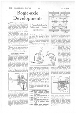
ANEW design of double-drive, twin rear axle is shown by R. Whitford, of Reo Motors, Ltd., Queen Street, Palmerston North, New Zealand, in patent No. 411,246. The chief feature is the method of mounting the axles, which allows free movement yet maintains, in all positions, a definite mechanical location.
The drawing shows a plan view of an axle, the springs being removed from one side. The axle tubes (1) are housed in split bearings attached to rigid beams (2), a longitudinal horizontal bearing (3) being interposed in each case. The beams (2) are pivoted on central brackets (4) attached to the chassis. Universal torque-rods (5) control the axle movement, whilst a torque tube (6) limits inter-axial deviation.
Thus it will be seen that the axles have a high degree of individual movement, at the same time being constrained to definite mechanical paths.
A Self-limiting Fuel Pump.
AFUEL-SUPPLY pump having a simple automatic means for limiting the supply to the requirements of the consuming unit, is shown in patent No. 410,537 by F. J. S. Jones, " Moreton," New Road, Porthcawl, South Wales. Pumps of this type are usually provided with a lost-motion device for shortening the effective stroke when pressure rises.; the same result is attained in this pump in a very simple manner.
The drawing shows a flexible diaphragm (1) gripped at its periphery and having a central boss carrying an arm (3) which is worked by an eccentric or cad. The diaphragm is held on to the, boss by two dished washers, and when the arm is oscillated, a point (2) on the periphery of the inner washer forms the fulcrum of movement.
When the interior pressure rises, owing to a lessened demand, the inner washer is lifted from its seat, against the spring pressure, and rocks idly on a cushion of liquid without changing the volume of the pump interior.
a4S
Further Progress in Trailer Brakes.
IN patent No. 411,977 the.. Eagle 'Engineering Co., Ltd.. Eagle Works, Warwick, discloses a novel mechanical means for taking up a slack cable preparatory to applying the brakes of a trailer.
In the drawing. the bottom end of the brake lever is connected to two pairs of toggle Maks (1) anchored on a pivot (2). At the mid pivots are two pulleys (3) around which a chain attached to the brake cable is passed, anchorage being made to one of the toggle links. In the " ofi " position the two pulleys are near, as shown in the left-hand drawing, but upon the lever being pulled to the " on" position, the pulleys are forced farther apart, which action takes up the slack and applies the brakes.
It is important to observe that the toggle movement achieves the important end of fast early movement, gradually increasing the leverage until it approaches its maximum when most required. The Elimination of Steering Backlash.
PATENT No. 411,758, by the Marks Steering Co., Ltd., Winchester House, Old Broad Street, London, E.C.2, describes a design of steering box, which, it is claimed, gives increased durability and practically eliminates backlash. Referring to the drawing, the steering column carries a hardened steel worm (1), the diameter of which is smallest in the middle, increasing towards the ends. Instead of the usual worm-wheel segment is a roller (3) having peripheral grooves formed to mate with the worm, This roller is mounted on needle roller hearings, in order to minimize friction; the whole assembly is carried in a fork attached to the rocker shaft.
It will be appreciated that there is a complete absence of rubbing friction in the wearing parts, roller bearings being used at all points, except in the bearings of the slow-moving rocker shaft. Adjustment is provided by mounting the roller (3) slightly on-centre with
respect to the worm (1), so that by bringing them closer together a fine adjustment may he obtained.
Wear between the roller and worm, however, should be small, probably less than that at the ends of the roller where the thrust is transmitted, but there should be no difficulty in taking up play here.