


The New Leyland Railcar.
Page 11
Page 12
If you've noticed an error in this article please click here to report it so we can fix it.
The Successful Application of a Large Petrol Engine and the Thomas Transmission System to a Main Line Railway Coach.
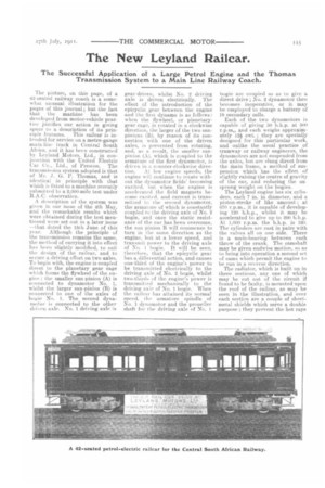
The picture, on this page, of a 42-seated railway coach is a somewhat unusual illustration for the pages of this journal; but the fact that the machine has been developed from motor-vehicle practice justifies our action in giving space to a description of its prin ciple features. This railcar is intended for service on a metre-gauge main-line track in Central South Africa, and it has been constructed b3 Leyland Motors, Ltd., in conjunction with the United Electric Car Co., Ltd., of Preston. The transmission system adopted is that of Mr. J. G. P. Thomas, and is identical in principle with that which is fitted to a machine recently submitted to a 2,000-mile test under R.A.C. observation.
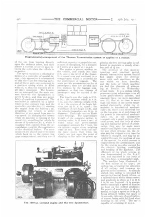
description of the system was given in our issue of the 4th May, and the remarkable results which were obtained during the test mentioned were set out in a later issue —that dated the 15th June of this year. Although the principle of the transmission remains the same, the met hod of carrying it into effect has been slightly modified, to suit the design of the railcar, and to secure a driving effort on two axles. To begin with, the engine is coupled direct to the planetary gear cage which forms the flywheel of the engine ; the smaller sun-pinion (A) is connected to dynamotor No. 1, whilst the larger sun-pinion (B) is connected to one of the axles of bogie No. 1. The second dynamotor is connected to the other driven axle. No. 1 driving axle is gear-driven, whilst No. 2 driving axle is driven electrically. The effect of the introduction of the epicyclic gear between the engine and the first dynamo is as follows: when the flywheel, or planetarygear cage, is rotated in a clockwise direction, the larger of the two sunpinions (B), by reason of its connection with one of the driven axles, is prevented from rotating, and, as a result, the smaller sunpinion (A), which is coupled to the armature of the first dynamotor, is driven in a counter-clockwise direc tion. AI. low engine speeds, the engine will continue to rotate without the dynamotor fields' becoming excited, but when the engine is accelerated the field magnets become excited, and current is transmitted to the second dynamotor, the armature of which is constantly coupled to the driving axle of No. 2 bogie, and once the static resistance of the car has been overcome, the sun pinion B will commence to turn in the same direction as the engine, but at a lower speed, and transmit power to the driving axle of No. 1 bogie. It will be seen, therefore, that the epicyclie gear has a differential action, and causes one-third of the engine's power to be transmitted electrically to the driving axle of No. 2 bogie, whilst two-thirds of the engine's power is transmitt ed mechanically to the driving axle of No. 1 bogie, When the raiinar has attained its normal speed, the armature spindle of No. 1 dynamotor and the propeller shaft for the driving axle of No. 1 bogie are coupled so as to give a direct drive ; No. 2 dynamotor then becomes inoperative, or it may be employed to charge a battery of 18 secondary cells.
Each of the two dynatnotors is capable of giving 50 b.h.p. at 500 r.p.m„ and each weighs approximately 12icwt. ; they are specially designed for this particular work, and unlike the usual practice of tramway or railway engineers, the dynamotors are not suspended from the axles, but are slung direct from the riaain frame, a method of suspension which has the effect of slightly raising the centre of gravity of the car, and reducing the un. sprung weight on the bogies. The Leyland engine has six cylinders, each 7 in. in diameter, and a piston-stroke of like amount ; at 050 r.p.m., it is capable of developing 120 b.h.p., whilst it, may be accelerated to give up to 200 b.h.p. At 1,000 r.p.m. the b.h.p. is 160. The cylinders are cast in pairs with the valves all on one side. There is a main-bearing between each throw of the crank. The camshaft may be given endwise motion, so as to bring into operation a second set of cams which permit the engine to be run in a reverse direction.
Tbe radiator, which is built up in three sections, any one of which may be cut out of the circuit if found to be faulty, is mounted upon the roof of the railcar, as may be seen in the illustration, and over each section are a couple of sheetmetal shields which serve a double purpose: they prevent the hot rays
of the sun from bearing directly upon the radiator tubes, and they induce a current. of air to pass between the coils when the vehicle is in motion.
The speed variation is effected by means of a controller of special design ; this apparatus is constructed HO that there are few wearing parts, and all these parts are contained in a cast-iron casing which is filled with oil, so that the contacts are at all times immersed. The brushes are so arranged that the main current between the dynamotors is never broken, and thus any possibility of sparking is prevented. The controller is operated by a handwheel in the ordinary way, and the controller provides for : (1), starting the engine from the battery ; (2). propelling the vehicle in either direction at any speed from zero to top speed ; (3). charging the battery while the machine is running at top speed ; (4), propelling the vehicle by means of dynamotor No. 2, which is supplied with current from the accumulators ; and (5), the application of the electrical brakes. The accumulators are placed under two seats which back up to the central luggage compartment, and they are of sufficient capacity to propel the ear, in case of emergency, for a distance of 8 miles at a speed of 4 m.p.h.
The engine is placed midway on the vehicle, and stands less than 2 ft. above the level of the frame. It is cased over and enclosed, in a compartment which is reserved for the conveyance of luggage. The seats provide accommodation for 42 passengers ; they are divided into two sections by the luggage compartment, so that two classes of passengers may be carried if desired.
The length over the body is 37 ft.
6 in. : the extreme width is 8 ft.
7 in., arid t he extreme height 10 ft. 10 in. : the centres of the bogie bolsters are 22 ft. 6 in. apart ; the wheelbase of each bogie is 5 ft., and the wheels themselves are 30 in. in diameter. Each axle runs on Hyatt roller bearings. The approximate weight of the complete railcar, in running order. is 21 tons 5 cwt., of which total the petrol-electric equipment accounts for 7 tons, the six-cylinder engine alone weighing sonic' 35 cwt. Tests with this railcar have shown that when the wheels are just upon the point of slipping on the rails the power ap plied at the two driving axles is sufficient to maintain a steady drawbar pull of 11 ton.
The inventor of this most-interesting and practical petrol electric transmission system should find ample scope for development with such machines as the
one which we here describe, and the tests of which machine we had the pleasure of witnessing at Preston on Wednesday of last week. It is a system which possesses great advantages over all other petrol-electric systems, and amongst these the more-important are: (1), that at no Limo is more than one third of the power transmitted electrically, whilst the remainder is transmitted mechanically; (2), there is no electrical loss on the top gear, as at such times all the power is transmitted mechanically ; (3). as the dynamotors transmit only a small portion. of the total power, and that only at starting and during the period of acceleration, they may be made much smaller and lighter than the motors for any other system ; (4), the engine may be stopped every time the vehicle is stopped, and may be restarted through the medium of one of the motors, for which current is supplied from the accumulator ; and (5). the system provides current for the electric lighting, ventilating and braking of the machine. The efficiency of the whole system, as was demonstrated in the
test, and reported in our issue of the 15th June, is remarkably high.
The machine here illustrated is the first railcar of its type ; the system has attracted the attention of all railway and tramway engineers in this country. As already stated, this railcar is intended for service in Central South Africa, on a railroad upon which sharp curves, and gradients as steep as 1 in 25 to
in 30. are frequent ; it is guaranteed to maintain a speed of 30 miles an hour on ehe stiffest gradients. Its power of acceleration is phenomenal, so high a speed as 30 m.p.h. being attained within the space of 30 seconds. this rate of acceleration. of course, being with full load when running on the level. The car is capable of attaining 50 m.p.h.