


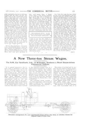
A New Three-ton Steam Wagon.
Page 5
Page 6
Page 7
If you've noticed an error in this article please click here to report it so we can fix it.
The S.M. Car Syndicate, Ltd., of Willesden, Produces a Novel Steam-driven Commercial Vehicle.
In its general appearanee. the vehicle which is illustrated on this and the two following pages, has no resemblance to the orthodox type of steam wagon or van. The views show a machine which has been built by the S.M. Car Syndicate, Ltd., of 9a, Hythe Road, Willesden Junction, N.W., after some four or five years. of experimental work—on the test bench, and with cars on the road-upon the system which is embodied in the oonstruction of the vehicle. So far aa the chassis itself is concerned, we need only state that it alosely conforms
to the generally-accepted lines of a modern petrol-engined lorry of similar load-carrying capacity; the builders have not attempted to make avery part " in our own works." but have selected proved components, such as a Butler's patent leading axle, and a worm-driven live back axle—the latter being supplied by Dennis Bros., Ltd., of Guildford.
The completed chassis presents a very clean appearance, and it has not nearly so much of the " pipeyness " which charaAerizes the majority of seperherited-steam vehicles.
The system of fuel-feed and its control, and the method of steam generation, with its use, expansively in a compound engine, should be of great interest to a large number of our readers. We are pleased, therefore, to be able to gi:,e the first-published description of this new commercial motor, for which A. A. Rupprecht and Co., Ltd., of 61-62, Carlton House, Lower Regent Street, S.W., has the sole selling rights: any inquiries should be sent to that address.
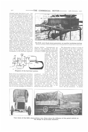
The generator is of the semi-flash type, with water-sealed coils; it is
situated under the driver's seat. One of our illustrations shows such a boiler, as used for testing purposes in the works. The generator is very low, and is very broad ; one result of its breadth is that a large area of tubing is exposed to the direct action of the flames from the burners. Chiefly on account of the large flame area, the burner need not be forced at any time, consequently, the tendency to burn out the generator tubes, which, in the past, has been one of the disadvantages attending the employment of a flash, or semi-flash generator, should bo greatly reduced. The water seal between adjacent coils also tends towards longer life for the tubes, as well as a moreregular rate of steam generation. The paraffin burner is divided into three separate compartments; two of these are for the main jets, whilst the third, which is quite small in size, serves as a pilot lamp for heating* the main vaporizer, and as a means of reigniting the main burners after they have, momentarily, been put out of action by the operating of either the thermostat or the fuel-feed regulator.
Each of the two main-burner chambers is provided with a separate fuel nozzle and mixing tube; these may be seen in the view of the generator. The actual burner jets consist of fine saw cuts through a number of small nickel grids, which are fitted in the top-plate of the burner. The vaporizer consists of a stout-steel casting, through which the oil and gas passages are drilled in
zig-zag fashion. Arrangements are made for the cleaning of both the vaporizer passages and the burner jets, by means of steam from the generator.
Of the two pipe diagrams which we reproduce, the first shows the fuel-feed system. The fuel is stored, under a pressure of about 70 lb. per sq. in., in a tank at the rear of the frame; the pressure on the surface of the oil is maintained by means of a pump that is driven from an m.centric on the forward end of the crankshaft. From the tank (A), the fuel is forced through a strainer (C), and thence to the pilot lamp, by way of the valve (D), and also to the main burners by way of a thermostat (E). a steam-pressure-controlled valve (F), and an adjustable valve (G). Steam, for clearing the passages in both vaporizers and burner jets, is admitted through the valve (H).
The thermostat is shown in front of the generator in the above reproductions, and another view shows its position when on the chassis; in the latter illustration, the bell-mouth of one of tho mixing tubes is also shown, together with its fuel-feed nozzle. The thermostat consists of two concentric tubes, the inner one of which is made of copper ; the annular space between the two tubes forms a part of the main steam pipe. The inner tube is free to expand independently of the outer one, and to one end of the copper tube a steel rod is attached, so as to transmit the movement, due to the difference in the rates of the expansion of the two tubes, to a multiplying lever which, in turn, actuates a cutoff valve in the fuel system. By means of this instrument, dangerous increases. in the temperature of the steam are avoided. In addition to the approximate control of their temperature, the burners are also regulated by the pressure of the steam : when the pressure rises above a pre-determined point, the fuel feed is interrupted until such time as the steam's pressure is reduced below the set maximum. A similar pressure operated regulator is employed in the water circuit, but, in the latter case, instead of its stopping the flow of the liquid, the water is merely by-passed back from the delivery side to the suction side of the feed pumps.
The second of the pipe diagrams will suffice to explain the water circuit. Water is drawn from the tank (X), through a strainer (K); it is then forced, by the main feed pumps M and N, through a feed-water heater (T and U), which is fitted in the top of the condenser (W). and on to the generator. When a pressure of 600 lb. per sq. in. is attained, the water is by-passed, from the pumps M and N, through the branch piece II, and the pressureoperated regulator V. The auxiliary pump L is only employed when the vehicle is climbing long hills with heavy loads ; at other times, water delivered by it is by-passed through the valve S. In the wagon which is Milstrated, the auxiliary pump L is not fitted, but procision is made for the by-passing of the. water delivered by the pump M, the pump N being capable of maintaining the supply during normal running. A hand-operated pump (0) is provided for starting purposes.
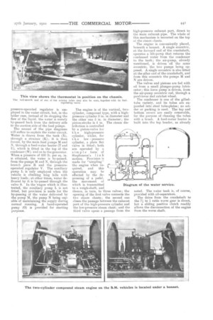
The engine is of the vertical, twocylinder, compound type, with a highpressure cylinder 8 in. in diameter and the other one in. in diameter; the piston-stroke is 4 in. The steam distribution is controlled by a piston-valve for t h e high-pressure cylinder, whilst, for t h e low pressure cylinder, a plain flat valve is fitted ; both are operated by a S imple form of Stephenson's iin k motion. Provision is made for "simpling" the engine when required, and this operation may be effected by the depressing of a. pedal, the movement of which is transmitted to n weigh-shaft, and thence, in turn, to three valves ; the opening of the first valve connects the two steam chests ; the second one closes the passage between the exhaust port of the high-pressure cylinder and the low-pressure steam chest; and the third valve opens a passage from the high-pressure exhaust port, direct to the main exhaust pipe. The whole of this mechanism is mounted on the top of the steam chests.
The engine is conveniently placed, beneath a bonnet. A single eccentric, at the forward end of the crankshaft, operates a lift-pump that returns the condensed water from the condenser to the tank ; the air-pump, already mentioned, is driven off the same eccentric, the two pumps being opposed. A single eccentric is also fitted at the after end of the crankshaft, and from this eccentric the pumps M and N are driven.
The valves and pistons are fed with oil from a small plunger-pump lubricator; this force pump is driven, from the air-pump eccentric rod, through a pawl-lever rind ratchet wheel.
The condenser is one of the gilledtube variety, and its tubes are expanded into steel tube-plates; no solder or packing is used. The top and bottom covers are easily removable, for the purpose of cleaning the tubes with a brush. A feed-water heater is built into the top header, as already
noted. The water tank is, of course, provided with oil-separators. The drive from the crankshaft to the 71 to 1 ratio worm gear is direct, but a sliding positive clutch readily allows the disconnection of the engine from the worm shaft.