


Patents Completed.
Page 20
If you've noticed an error in this article please click here to report it so we can fix it.
Complete specifications of the following patents will be sent to any address in the United Kingdom upon receipt of eightpence per copy at the Sale Branch, Patent Office, Holborn, W.C.
LUBRICATOR.—Royee.—No. 5,291, dated 4th March, 1909.—The object of this invention is to control the supply of lubricant to the engine by the fluctuations of pressure within the induction pipe, and, therefore, to regulate the limy
of lubricant so that it will he proportionato to the load. The induction pipe is in communication orith a small cylinder in which is mounted a piston. Concentrically formed with the piston is a plunger which is adapted to be reciprocated within an extension of the cylinder by the piston, The plunger has a
reduced portion, whiell forms an annular space within the extension, aod this annular space is adapted to establish communication between the lubricant-supply pipe and the pipe leading to the engine. It will be seen that the plunger operates to shut off the supply of oil to the engine when the vacuum in the induction pipe increases, and to open the supply again when the suction effort is reduced.
FIRE-BOX FOR STEAM GENERATORS.—Clayton and ShuttIeworth. Ltd., and Another.—No. 7,404, dated 27th March, 1909.—This invention relates to steam generators of the locomotive type,
and, especially, to those employed with portable engines or road locomotives. The object of the present invention is to provide means whereby the fire-box may be readily adapted for various kinds of fuel, such as coal, wood, peat, sawdust, shavings and the like. A baffle plate is pivotally mounted within the firebox iu such manner that it may lie fiat on the grate bars or may he turned into a vertical position so as to cover or protect the fire-tubes. This baffle plate has a number of slots formed therein which allow the flames to pass through the latter when in a vertical position, and the same sluts serve as air spaces when the baffle plate is lying on the grate bars. When shavings or straw are being burnt, the baffle plate is turned into a vertical position so as to prevent any charred straw or shavings from clog. ging the fire tubes. When coal is being consumed, the baffle plate is turned down on to the grate bars, and it will be noticed that, in so doing, the grate area will be increased.
TAXIMETER.—Ohmer.—No. 27,806, dated 21st December, 1908.—According to this invention mechailisin is provided for printing upon a ticket the following data :—The time at. which the vehicle is hired and the time when the journey is finished, the amount of fare due, the date when the ticket is issued, the identification number or mark by which the driver is identified ;Ind a duplicate record thereof, the consecutive number of each ticket and the sum or amount due for extra charges, such for example as baggage, etc. The object of this is to reduce to a minimum the risk of disputes between the driver of the vehicle and the public. It is intended that the ticket, should be handed to the passenger at tho completion of a journey or " hiring."
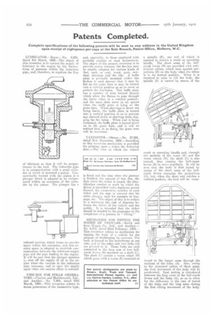
MECHANISM 18'011. TIPPING THE BODIES OF .VERICLES.—STnith and Sons Wagou Co.. Ltd_ and Another.— No. 4,315, dated 22nd February, 1909.— This invexition relates to mechanism for tipping the body of a vehicle for the purpose of discharging its contents. The body is hinged to the underframe at one side, and et the other side two links (A) are pivoted to it. These links are each connected to the long arm of two bellcrank levers (13) mounted on a shaft (C). The shaft (C) carries a worm wheel (D) which gears with a worm (E) mounted on
a spindle (F), one end of which is squared to receive a crank or operating handle, The short arms of the hellcrank levers (B) are provided with antifriction rollers, which bear against projections (G) on the body when the latter is in its normal position. When it, is required to raise or tilt the body, the spindle (V) is turned by means of the
crank or operating handle and, through the medium of the worm (E) and the worm wheels (D), the shaft. (0) is also turned, thus causing the hell-crank levers (B) to move angularly. It will be seen that the body is first raised by means of the short, arms of the bellcrank levers engagiug the projections (G), but, when the short arm reaches a vertical position, the load will be trans
ferred to the longer arms through the medium of the links (A). Also, owing to the increased radius of these arms, the filial movement of the body will be accelerated. Lost motion is introduced between the long arms of the bell-crank levers and the links (A), so as to allow for the difference in the rate of travel of the links and the long arms during the first tilting movement of the body.