


Two New Machine Tools.
Page 16
Page 17
If you've noticed an error in this article please click here to report it so we can fix it.
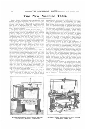
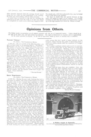
We are pleased to be able to give, on this page, illustrations, and brief descriptions, of two new and useful machines suitable for the repair shops of owners of fleets of vans. One of these, a small-size, ball-bearing radial drill, is built by Alfred Herbert, Ltd., of Coventry, and the other is a new double-bedded lathe, produced by Mr. Henry Milnes, of Bradford.
The drilling machine is capable of taking drills up to I in. in diameter ; the maximum radius of action is 37 in., and the greatest height of work admitted above the table is 221 in. There are six spindle speeds, the slowest one being suitable for tapping, facing, or counter-boring boles. The highest speed of the drill, of about 2,030 r.p.m., may be obtained without a very-high belt velocity. Every spindle on the machine is mounted on ball bearings and, consequently, a mininenn of power is required for driving. The twin-bed lathe illustrated herewith has been modelled on the lines of Mr. Milnea' " Class N " screwcutting lathes, and, in fact, many of the parts of that type are employed in the new model, but the various attachments shown have been added in order to render the machine universal in its applications.
The carriage, with its compound slide-rest, is fitted on the front part of the bed, as may be seen in the view, but the poppet head slides on a second bed, behind that which bears the carriage and the fixed head-stock. This form of construction enables the carriage to be racked past the 'poppet head, thus removing the necessity to take the job out of the centres when the slide-rest has to be removed and the hand-rest put in position. The transverse slide on the carriage is provided with tee slots; it may thus be used as an adjustable boring table. The top part of the slide-rest is fastened to the swivel slide by a siugle boll, and it may easily be taken off, when not required. The under, or circular part, of the swivel slide is fitted into a ring on the carriage, and it has graduations for setting the slide to any angle, for taper work. The top slide, in addition to a " Willis " tool holder, is provided with a socket, and an elevating tool pest., or holder, and this is so fitted that either can be used at will. A quick withdrawing motion, of improved design, with adjustable micrometer, is fitted to the transverse, or lower slide on the carriage. A worm wheel, with a tangent screw, is fitted to the head-stock, and nine micrometer collars, of various sizes, are supplied ; by means of these it is possible to divide all numbers except prime numbers, There is also fitted, to the front gear wheel in the head-atock, a dividing-plate with a spring stop, also arranged with a micrometer adjustment. On one end el the head-stock is fitted an arrangement, by the use ot which the leading-screw may be used for sliding, no matter what the change-wheels may be on the lathe. By means of this attachment, it a screw of any particular pitch is being cut, the swing frame, or quadrant plate, may be loosened, by means of an adjustable nut; it may then be pushed down out of the way, and again fixed. The saddle is then ready for automatic sliding, or surfacing.
The gearbox, as may he seen in the illustration, is fastened to the front of the bed, underneath the headstock; this is arranged to give three rates of saddle travel for each combination of change-wheels. The lever by which the gears are controlled is moved either to the right or left, to bring the different gears into action. A brake, for stopping the lathe suddenly, is also provided, and, by pressing down a foot lever, the brake is caused to act on the flywheel. The overhead apparatus possesses a rather novel feature: it is so fitted that when the carriage slides along the bed, the leading-screw on the bed drives a similar leading-screw on the overhead motion; by this means, the overhead cone and the belt tension pulleys are caused to travel along the shafts at the same speed as the slide-rest carriage.
The crankshaft is arranged for a power drive in addition to the treadle motion. The leading screw may be driven, from the tail end of the lathe, by means of chain wheels and chain from the crankshaft ; the introduction of an intermediate shaft provides for the fitting of different change-wheels for this auxiliary drive. A swing frame, or quadrant plate, is arranged on the leadingscrew tail bearing, similar to that fitted at the other end of the screw. This attachment is very convenient
when necessity demands that the carriage should travel along the hea while the fast head-stock is not running. as is the case when milling, and for other purposes. A metal tray is fastened to the bed for catching the lubricant as it falls from the work ; it is also very useful as a receptacle for small screws which may happen to fall. The steady-rest, with three adjustable dies, may be bolted down to the bed in any position.
We have no doubt that the special features of this lathe will appeal to many of our readers. It is hardly necessary to add that the quality of workmanship is quite up to the high standard for which Mr. Milnes is noted.