


Overdrive for Heavies
Page 66
If you've noticed an error in this article please click here to report it so we can fix it.
'ATENT No. 807,425 shows an overdrive mechanism for heavy vehicles with overhead-worm-type, double-drive rear bogies. (Kirkstall Forge Engineering, Ltd., Kirkstall Forge, Leeds, 5.)
The usual arrangement of a twin-axle drive comprises a front axle driven from the gearbox and a back axle driven through the front one, with a differential gear interposed in the coupling shaft. Substantially the same layout is used, but the inter-axle differential gear is ingeniously modified to act as an overdrive when required.
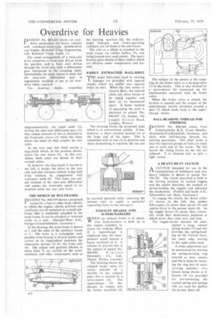
The drawing shows, somewhat diagrammatically, the input shaft (1), driving the inter-axle differential gear (2). One output element of this is attached to the front-axle worm (3) while the other drives the shaft (4) that couples the two axles.
At the rear end, this shaft carries a dog-clutch which, in the position shown, drives the rear worm (5). In this condition, both axles arc driven at their normal ratios.
If, however, the dog-clutch is moved to the left, it breaks the drive to the rear axle and also becomes locked, being held from rotation by engagement with stationary teeth (6). This locks one output element of the inter-axle differential and causes the front-axle speed to be doubled while the rear axle trails.
THE DESIGN OF BUS FRAMES D ATENT No. 806,939 shows a proposed I layout for a bus or other large vehicle, in which the engine, clutch, gearbox and auxiliaries are all mounted on a small subframe that is ' resiliently attached td the main frame. It can be attached or removed easily as a unit. (Daimler-Benz A.G., Stuttgart-Untertilrkl3eim, Germany.)
In the drawing, the main frame is shown at 1 and the sides of the auxiliary frame at 2. The latter is a rectarigular unit, sturdily cross-braced at several points and carries on its longitudinal members the suspension springs (3) for the front axle (4). The engine and gearbox (shown in chain lines 5) are carried on the crossmembers, and other components such as the steering gearbox (6), the radiator, pedal linkages and brake-operating cylinders, are all fixed to the sub-frame.
The unit as a whole is attached to the main frame via rubber buffers (7), one being located near each corner. The specification gives details of these buffers which are effective under compression and tension.
EASILY EXTRACTED BALL-JOINT
TilE usual ball-joints used in steering linkages are provided with tapered shanks which arc pulled into tapered bores by nuts. When the time comes to remove them, the tapered joints are often found to be rusted together and have to be hammered apart. A better method of separating the joint is disclosed in patent No. 806,897. (A. Jordan, 34a Langley Green Road, Langley, Worcs.)
The drawing shows the proposed joint which is of conventional outline. It has, however, a short screwed portion (1) at the large end of the taper. This is assembled with its'nut (2) in position and when dismantling is required, the nut can be screwed upwards (after removing the normal nut) to apply a powerful separating force to the two parts.
EXHAUST BRAKES AND SUPERCHARGERS
WHEN an exhaust brake tion, back-pressure is the engine cylinders to create the braking effect. If a supercharger is employed also, the back' pressure could impose a heavy overload on it. A scheme to prevent this is the subject of patent No.
806,900. (Clayton Dewandre Co., Ltd., Titanic Works, Lincoln.) The drawing shows the exhaust brake valve (1) which consists of a throttle in the exhaust pipe; this is worked by a servo-motor (2). The supercharger (3) discharges its output into the intake manifold (4). The subject of the patent is the coupling of the brake valve to a by-pass valve (5) in the intake. This is also worked by a servo-motor (6) connected up for simultaneous operation with the brake valve.
When the brake valve is closed, the by-pass is opened and the output of the supercharger merely circulates around a duct (7) which leads back to the supercharger intake.
BALL-BEARING THREAD FOR STEERING ATENT No. 808,260 comes from Fulminawerke K.G. Franz Mueller. Mannheim-Friedrichsfeld, Germany, and deals with ball-bearing threads for steering gearboxes. The chief point is that two separate groups of balls are used, one at each end of the screw. By this layout the tilting forces on the nut are reduced. It is claimed also to give a light action.
A HEAVY-DUTY CLUTCH
A CLUTCH intended for use in the /—i transmissions of bulldozers and very heavy vehicles is shown in patent No. 796.785. The clutch described is held in the driving position by locked toggles and the patent describes the method of spring-loading the toggles, and adjusting the mechanism. (Fichte! and Sachs A.G., Schweinfurt am Main, Germany.) To engage the clutch, the thrust collar (1) moves to the left; this pushes bell-cranks (2) about their pivots (3) and applies force to the presser plate (4). As the -toggle levers (5) move, they eventually reach their dead-centre positions at which point they rock over and lock.
The toggle-carrier member (6) abuts against a large, conical spring washer (7) and this provides the spring-loading on the friction faces, the inner edge moving to the right under load.
A close adjustment can be maintained by moving the spring-carrying ring inwards as wear occurs, and this is done by screwing the ring into its outer carrying member, t h e thread being shown at 8. Screws (9) are provided for pre-tensioning the conical spring and springs (10) are used for pulling the presser plate off.