


Patents Completed.
Page 20
If you've noticed an error in this article please click here to report it so we can fix it.
Complete specifications of the following patents will be sent to any address in the United Kingdom by the Sales Branch, Patent Office, Holborn, W.C. upon receipt of eightpence per copy.
A holotorhus Lamp.
The London General Omnibus Co., Ltd., and W. R. Crofts, No. 7261, dated 25th March, 1912.—A lamp suitable for use on motorbuses and like vehicles, is so arranged that it illuminates a sign or route-board directly, and at the same time illuminates a acreen by transmitted light, both sign and screen being arranged so as to be exhibited in the same direction. The lamp is of the shape shown in the accompanying drawing.
The back is opaque, and is sloped at a steeper angle -than is the top of the lamp. The light is placed well in the middle of the lamp, and is accessible through a door in the back, and it, is thrown forward through the screen and backward on to the route-board.
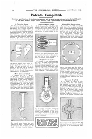
A New Clarkson Wheel.
T. Clarkson, and W. J. -Morison, No. 784, dated 7th March, igia—This specification describes a construction of metal wheel for road vehicles, especially those of the heavy type. The design is such that the whole wheel can be made of forged metal. A forged hub is provided with a number of radial bosses which are bored out and machined hat, Hard drawn steel tube spokes are welded to these bosses, and end pieces which
live curved lateral flanges are butt weldedto the spokes. The outer ends of the spokes are then machined, and the rim is welded and riveted in position.
Steering-wheel Pivots.
E. S. Alexander, No. 1418, dated 18th January, 1912.—The front axle of a chassis extends from centre to centre of each front wheel, and is provided with ball bearings for pivots formed on the bushes of each of the wheel axles. Rods are mounted on the side of these bushes, and are bent to form bell-cranks, to which the steering rod is coupled.
A Light Stearn Engine.
H. Pearson, P. Cox, and Pearson and Cox, Ltd., No. 6064, dated 11th March, 1912.—This specification describes a construction of steam engine in which considerable reduction of weight and size is achieved. The engine is of the singleacting type with a trunk piston and enclosed crankcase. The transmission pul ley or sprocket is mounted outside the crankcase. The special feature of the engine is the operation of the valves through bell-crank levers by cams on the crankshaft, so that constructional simplicity is obtained.
Piston Ring Construction.
M. S. Gibb, No; 9104, dated 17th, April, 1912.—This invention has for itsobject to provide a means for adjusting the pressure which piston rings exert upon the wall of the cylinder. Each ring is in two parts, which have their joints diametrically opposite oneanother. The lower ring has two slots, one on either side of the joint, and theupper ring is fitted with dowels, the posi
tions of the dowels and slots being so arranged that the expansion of each ring is limited. When it is desired to allow the ring to expand further, the slots may be lengthened a suitable amount. This is most conveniently done by fitting crescent-shaped packing pieces of brass in the slot originally, and filing them down as required.
Universal Coupling.
W. H. Hardy, No. 24,181, of 1911, dated 30th April, 1912.—This specification describes a universal coupling of the ball-and-socket type in which a greater degree of freedom than usual is obtained. A groove is formed in the usual way in the ball, and a gimbal lying in the groove is trunnioned in the socket. The special feature of the construction is that the curvature of the bottom of the groove is sharper than
the curvature of the gimbal, so that they only touch for a short distance, as clearly illustrated in the accompanying drawings.