


Starter motors, 2
Page 34
If you've noticed an error in this article please click here to report it so we can fix it.
ECAUSE the starter motor has ly intermittent use, bronze ishes are used to carry the mature shaft instead of the lI races which are used on dym Os
To avoid excessive voltage .op, the cables connecting the 3tte ry to the starter motor must 3 kept as short as possible and f a size adequate to carry the aavy current which is present 'hen the starter is in use and, in articular, when the engine is eing started from cold.
Starter cables vary from 7/0.71 (37 strands each 0.71mm diameter) for small engines to 1/1.13(61 strands each 1.13mm diameter) for large diesels.
lf the main starter cables were iken to a starter switch within• ie reach of the driver, the cable 'ould be excessively long. To void this it is common practice a use a solenoid near to, or on, le starter itself. The solenoid is, effect, a remote control deice.
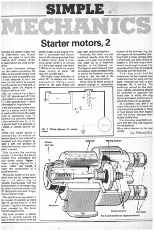
When the starter switch is perated by the driver an lectrorhagnet in the solenoid is nergised and this magnet at'acts a soft iron plunger to Mich the moving contact of the witch is joined.
This causes the moving ontact to bridge the fixed ontacts thus completing the -lain starter circuit. Figure 1 hows a wiring diagram for a tarter motor and Figure 2 bows the construction of a ypical solenoid.
The starter switch on the dashaoard may be an independent pale or, on petrol engine 'ehicles, incorporated with the gnition switch. in the latter case, he switch has three positions (1) aff; (2) ignition only and (3) igniion and starter motor.
The switch is spring-loaded in he number (3) position so that it eturns automatically to the lumber (2) ignition only position vhen released by the driver vhen the engine fires.
The main problem in starter iesign is centred around the vay in which the drive from the starter motor to the engine flywheel is connected and disconnected after the engine has fired. A starter motor gives it maximum power when it is running at a fairly fast speed, say about 1,500 revs/min, while the engine needs turning at about 100 revs-min in order start.
Obviously, a gear reduction of about 15:1 is needed, and this is achieved by fitting a small pinion to the start motor and gear teeth to the flywheel rim.
Generally, the teeth are not machined directly onto the flywheel, but a gear ring is shrunk into place up to a machined shoulder on the flywheel rim. The flywheel teeth become worn at localised spots corresponding to where the flywheel normally comes to rest, the rest of the teeth being in good condition.
When wear at these points is serious enough to necessitate renewal of the flywheel ring, the old ring can be removed by splitting it with a chisel perhaps after a small hole has been drilled to weaken it. The new ring is then heated just enough to cause it to expand so that it can be dropped into place over the flywheel.
The ring must not be overheated as the original heat treatment may be upset and the teeth rendered too soft to give adequate life in service. The workshop manual for the particular vehicle concerned should be consulted to ascertain the exact heat to which the ring should be heated and the way in which the heat is to be applied.
As a general rule, and if no exact information is at hand, the ring should be polished in three or four places and then heated until the colour changes from purple to dark blue.
It is, of course, essential to ensure that the ring sits squarely on the flywheel.
More about starters in the nexi
article. by Preceotor