


Swashplate Transmission Gear
Page 50
If you've noticed an error in this article please click here to report it so we can fix it.
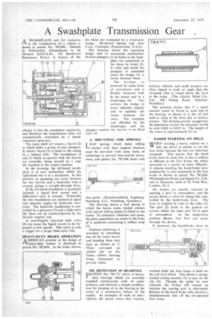
rtA SWASH PLATE unit for inclusion in the transmission of a vehicle is shown in patent No. 785,846. (Socidte de Fabrication d'Armements et de Moteurs S.O.F.A.M., 136 Boulevard Hausmann. Paris.) A feature of the
scheme is that the swashplate angularity, and therefore the transmission ratio, are automatically controlled by a speedresponsive governor.
The input shaft (I) rotates a barrel (2) in which slides a group of nine plungers. A similar barrel (3) is fixed to the casing by a splined tube. The swashplates (4 and 5) which co-operate with the barrels are rotatable, being carried on a cage (6) attached to the output member.
In the drawing, the left-hand swashplate is at zero inclination, whilst the right-hand one is at a maximum. In this position no pumping can occur between the two barrels and a hydraulic lock is created, giving a straight-through drive.
If the left-hand swashplate is gradually inclined, a liquid flow occurs and a differential ratio is created. Preferably the two swashplates are inclined at equal and opposite angles by hydraulic actuation. The hydraulic mechanism is controlled by a governor (7) and a slide-valve (8); these can be counteradjusted by the throttle control rod.
A centrifugally operated slide valve (9) can cause the liquid circuit to be bypassed at low speeds. This valve is only a trigger for a larger slide-valve (10).
HEAVY-DUTY BRAKE OPERATION
AMERMAN practice in the design of heavy-duty brakes is disclosed in patent No. 785.864. In the brake shown
the shoes are expanded by a transverse wedge.. (Rockwell Spring and Axle Corp., Coraoplis, Pennsylvania, U.S.A.) The drawing shows the operating wedge and its associated mechanism. Hollow plungers (I) in bores in the backplate are connected to the shoes by struts (2). A roller unit inside the plungers is expanded when the wedge (3) is thrust between them.
The wedge is powered by some form of servomotor and is flexibly Mounted both in the motor and in a
diaphragm (4). This permits the wedge to move sideways slightly and so equalize the thrust between the shoes. The complete seal afforded by the diaphragm and the plungers enables the interior to be filled with oil.
A MOUNTING FOR SPRINGS T EAF springs which make rolling contact with their support brackets must be provided with some form of anchorage to prevent fore-and-aft movement, and patent No. 785,404 deals with
this point. (Maschinenfabrik AugsburgNurnberg A.G., Nurnberg, Germany.) The drawing shows a leaf spring in which the leaves make loaded contact with curved rolling plates (I) fitted to the frame. To eliminate vibration and noise, the plate assemblies arc made in the form of a sandwich containing a rubber strip (2).
Endwise anchorage is provided by extending two of the lower leaves and bending them into eyes as shown at 3. These surround an anchor pin on the frame, rubber sleeving being interposed to prevent rattle.
OIL RETENTION IN BEARINGS DATENT No. 785,717 refers to heavyduty bearings which are normally supplied continuously with oil under pressure, and discloses a simple modification for keeping oil in the bearing in the event of a momentary failure of the supply. As examples of such an interruption, the patent states that tractors, military vehicles and earth scrapers are often tipped to such an angle that the oil-pump inlet is raised above the level in the sump. (The Glacier Metal Co., Ltd., 368 Ealing Road, Alperton, Wembley.) The patentee claims that if a small annular recess be bored in each end of the bearing, as shown at I, the MI will tend to cling to the bore due to surface tension. The drawing greatly exaggerates the dimension; in fact the clearance would be only 0.003 to 0.015 in. The length of the recess is approximately 0.1 in.
EASIER STARTING ON HILLS
WHEN starting a heavy vehicle on a hill, the driver is unable to use the foot brake because his feet are otherwise occupied. This means that the hand brake must be used, but, as this is seldom so efficient as the foot brake, the whole operation is a matter of some difficulty. A scheme enabling the hand-brake lever temporarily to take command of.the foot brake is shown in patent No. 785,620. (Westinghouse Brake and Signal Co., Ltd., and A. Simmons. both of 132 York Way. London, N.1.) Air .brakes are usually released by opening a port to atmosphere, and the patent shows a valve for doing this, controlled by the hand-brake lever. The lever is coupled by rods to the yoke (I). The port (2) leads to the general air system. whilst the other port (3) is open to atmosphere. In the inoperative position shown. free flow can occur through (lee device.
If, however, the hand-brake lever be worked while the foot brake is held on. the rod (4) is lifted. This allows a springloaded sealing member (5) to seat on the rim (6). Though the pedal be now released, the brakes will remain on because the venting port is obstructed. Release of the hand brake will, therefore. simultaneously take off the air-operated foot brake.