


SEMI—PNEUMATIC SUSPENSION.
Page 32
If you've noticed an error in this article please click here to report it so we can fix it.
A Résumé of Recently Published Patents.
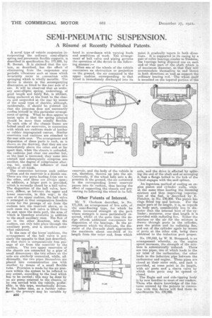
A novel type a vehicle suspension incorporating the ordinary semi-elliptic springand pneumatic flexible supports, is described' in specification No. 171,055, by R. Bernet. it is claimed that the system, as described, has the effect of eliminating from the suspension any periodic vibrations such as tnose which invariably occur in . connection with springing which is wholly metallic. The device is shown in the accompanying illustration as fitted to the rear axle of a car. It will be observed that an ordinary. semi-elliptic spring, underslung, of good length and fairly flat, is utilized, being anchored at the front to the chassis and suspended at the rear by means of the usual type of shackle, although, incidentally, it should he pointed out that the patentee does not necessarily confine himself to this particular arrangement of spring. What he does appear to insist upon is that the spring selected should be more than usually flexible. To each side of the chassis 'frame are belted small air reservoirs, in connection with which are cushions made of leather or rubber impregnated canvas. Similar reservoirs and cushions are attached to the rear axle case. The arrangement and disposition of these parts is such, as is shown on the draWing, that they are one immediately above the other and so far apart that., when the chassis is unloaded, the cushions just clear one another but, as the load is increased, they 'come into contact and subsequently cbmpress one another, the degree of compression altering, too, under the influenbe of road shocks of all kinds.
The connection between each rubber cushion and its reservoir is a double one. There are tiny ports leading i'rorn one to the other, and these are always open; in addition, a larger port is provided, which is normally closed by a ball valve. The dispositionof the ball valve, however, differs, as between the upper and lower reservoirs, in this way: in the case of the upper cushion, the ball valve , is arranged so that comparative freedom exists for the passage of air from the -cushion into the reservoir above, as in such cases the ball valve is lifted from its seat upon the main port, the area of which is therefore available in addition to the small auxiliary ones. The flow of air in the other direction, into the cushion, can only take place through the auxiliary ports, and is therefore some what restricted. . , •
In the case of the lower cushions, the arrangement of the ball valve is precisely the opposite to that just described, so that there is comparatively free passage of air from the reservoir to the cushion. The two upper reservoirs of the chassis are connected by a pipe of small dimensions: the two others on the axle are similarly connected, while, additionally, the two pipes themselves are placed into communication one with another by means of a small flexible tube. Provision is made for the air pressure within the system to be inflated to any extent, according to the load which has to be carried; this may be done by an air pump external to the chassis or by one carried with the vehicle, preferably, in this type, mechanically *driven. 'In the latter case, as a further refinement, the pressure -may b3 variable by .1350
hand in accordance with varying loads and eoeditions of work. The arrangemerit of ball valve and piping governs the operation of .the device in the following manner When one of the wheels of theVehicle . . encounters an obstruction or projection on the ground, the air contained in the upper cushion corresponding to that Wheel is immediately discharged into its reservoir, and the body of the vehicle is not, therefore, thrown up into the air. Conversely, if the wheel falls into a depression in the ground, the air contained in the corresponding lower reservoir passes into its cushion, thus having the effect of supporting the chassis and pre. venting its following the wheel in its fall.
Other Patents of Interest.
Me T. Clarkson describes, in No. 171,316, an arrangement of live axle, of the semi-floating type, for which he claims increased strength at the part where strength is more particularly required, whilst at the same time the design' affords, additional convenience for disposition of the bearings. In the arrangement which we illustrate, the diameter of the live-axle shaft approaches the maximum about one-third of its length from the ouster end, from which point it gradually tapers in both • directions. It is supported in its casing by a pair of roller bearings similar to Timkens, the bearings being disposed one on each end of that part of the shaft which is of maximum diameter, so that They will accommodate themselves to end thrust M both directions as well as support the ordinary bearing red. The wheel itself is mounted on the tapered portion of the axle, and the drive is effected by ing the end of the shaft and so arranging it that a flange bolted to the hub of the wheel engages with the said splines.
An ingenious method of cooling an engine piston and cylinder walls, while at the same -time heating the incoming mixture and thus improving vaporization of the fuel, is described by E. Fletcher, in No. 170,909. The piston has rings fitted top and bottom. For the major-part of Its length, it is, as regards its body part, considerably less in diameter than the internal bore of the cylinder; moreover, over that length it is provided with ra,diat_ing fins. Either the mixture or the air for the mixture is drawn through ports in the cylinder, past the piston and its radiating fins, and out of the cylinder again by means of ports at, the other side, being there admitted to the induction port proper.
No. 170,910, by W. If. Sheppard, is an arrangement whereby, as the engine speed increases, the strength of the mix ture is automatically reduced. There are two pipes, one of which leads to the air inlet of the carburetter, the other leads to the induction pipe between the carburetter and engine. These pipes are closed at their outer ends, and each is provided, at some point in its length, . with air ports and a sleeve valve by which these ports may be opened or closed.
The Eagle end and side-tipping body is by now familiar to most of our readers. Those who desire knowledge of the features covered by the patents in connection with this device will find them in epecification No. 170,992. •.