 1
1 2
2 3
3 4
4 5
5 6
6 7
7 8
8 9
9 10
10 11
11 12
12 13
13 14
14 15
15 16
16 17
17 18
18 19
19 20
20 21
21 22
22 23
23 24
24 25
25 26
26 27
27 28
28 29
29 30
30 31
31 32
32 33
33 34
34 35
35 36
36 37
37 38
38 39
39 40
40 41
41 42
42 43
43 44
44 45
45 46
46 47
47 48
48 49
49 50
50 51
51 52
52 53
53 54
54 55
55 56
56 57
57 58
58 59
59 60
60 61
61 62
62 63
63 64
64 65
65 66
66 67
67 68
68 69
69 70
70 71
71 72
72 73
73 74
74 75
75 76
76 77
77 78
78 79
79 80
80 81
81 82
82 83
83 84
84 85
85 86
86 87
87 88
88 89
89 90
90 91
91 92
92 93
93 94
94 95
95 96
96 97
97 98
98 99
99 100
100 101
101 102
102 103
103 104
104 105
105 106
106 107
107 108
108 109
109 110
110 111
111 112
112 113
113 114
114 115
115 116
116 117
117 118
118 119
119 120
120 121
121 122
122 123
123 124
124 125
125 126
126 127
127 128
128 129
129 130
130 131
131 132
132 133
133 134
134 135
135 136
136 137
137 138
138 139
139 140
140 141
141 142
142 143
143 144
144 145
145 146
146 147
147 148
148 149
149 150
150 151
151 152
152 153
153 154
154 155
155 156
156 157
157 158
158 159
159 160
160 161
161 162
162 163
163 164
164 165
165 166
166 167
167 168
168 169
169 170
170 171
171 172
172 173
173 174
174 175
175 176
176 177
177 178
178 179
179 180
180 AN ALBION 10-TON SIX-WHEELER
Page 128
Page 129
If you've noticed an error in this article please click here to report it so we can fix it.
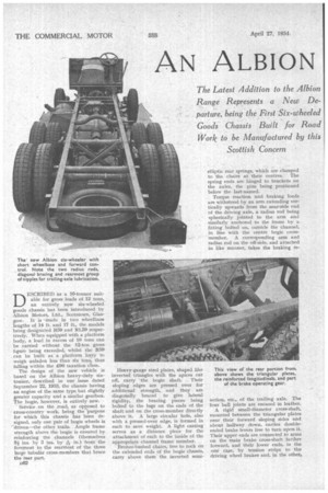
DESCRIBED as a 10-tonner suitable for gross loads of 12 tons, an entirely new six-wheeled' goods chassis has been introduced by Albion Motors, Ltd., Scotstoun, Glasgow. It is 'made in two wheelbase lengths of 14 ft. and 17 ft., the models being designated R59 and RL59 respectively. When equipped with a platform body, a load in excess of 10 tons can be carried without the 12-ton gross figure being exceeded, whilst the R5.9 can be built as a platform lorry to weigh unladen less than six tons, thus falling within the £90 taxation class.
The design of the new vehicle is based on the Albion heavy-duty sixtonner, described in our issue dated September 22, 1913, the chassis having an engine of the same type but slightly greater capacity and a similar gearbox. The bogie, however, is entirely new.
' Service on the road, as opposed to cross-country work, being the purpose for which this chassis has been designed. only one pair of bogie wheels is
'driven—the other trails. Ample frame strength above the bogie is ensured by reinforcing • the channels (themselves 9-i ins. by 3 ins. by Ain.) from the foremost to the rearmost of the three large tubular cross-members that brace the rear part.
D62 • Heavy-gauge steel plates, shaped like inverted triangles with the apices cut off, carry the bogie shaft. Their sloping edges are pressed over for additional strength, and they are diagonally braced to give lateral rigidity, the bracing pieces. being bolted to the lugs on the ends of the shaft and on the cross-member directly above it. A large circular hole, also with a pressed-over edge, is formed in each to save weight. A light casting serves as a distance piece for the attachment of each to the inside of the appropriate channel frame member.
Bronze-bushed chairs, free to rock on the extended ends of the bogie' chassis, carry above them the inverted semi elliptic rear springs, which are clamped to the chairs at their centres. The spring ends are hinged to brackets on the axles, the pins being positioned below the last-named.
Torque reaction and braking loads are withstood by an arm extending vertically upwards from the near-side end of the driving axle, a radius rod being spherically jointed to the arm and similarly anchored to the frame by a fitting bolted on, outside the channel, in line with the centre bogie crossmember. A corresponding arm and radius rod on the off-side, and attached in like manner, takes the braking re action, etc., of the trailing axle. The four ball joints are encased in leather.
A rigid small-diameter cross-shaft, mounted between the triangular plates near their forward sloping sides and about halfway down, carries doubleended brake levers free to turn upon it. Their upper ends are connected to arms on the main brake cross-shaft farther forward, and their lower ends, in the one case, by tension strips to the driving wheel brakes and, in the other, by push rods to those on the trailing wheels. Each rod and strip has a separate adjustment, whilst master adjusters are provided, in accessible positions, on the main foot and handbrake pull rods.
The rear brake drums are 161 ins, in diameter, and the shoes 61 ins. wide ; on the front wheels the latter dimen
sion is 2+ ins. brakes afe applied by , the _pedal, through the Dewandre triple servo system, the hand lever -bringing into action only the brakes on the bogie wheels.
The Transmission Layout. .
'Ile driving axle is a standard component of the overhead-worm type, incorporating a -steel worm and bronze wheel, giving a reduction of 8i to 1. An open tubular propeller shaft transmits the drive from a separately mounted four-speed gearbox. On the long-wheelbase machine a centre bearing and three mechanical universal joints are employed ; on the short model a single shaft is used. Variations in distance between the gearbox and axle are permitted by a telescopic joint inthe shaft, the working part being enclosed in leather.
For easy removal the gearbox is suspended from two channel-section cross members. The ends of these rest on rubber pads supported by angle brackets bolted to the frame longitudinals. Between clutch hnd gearbox there is a short shaft, having two fabric couplings. A feature of the clutch, which is of the single-plate type, is that the facings are riveted to the flywheel and pressure plate.
It is . of ,note–that every'important bolt used in the construction of the frame and bogie has a split=piniied nut. Bolts, incidentally, are employed almost exclusively, practically, the only rivets being those which secure the channel reinforcement. ,The edges of these are also welded to the main
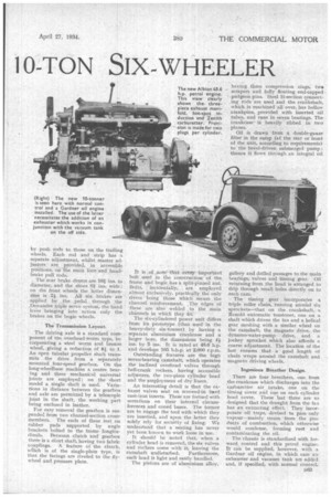
channels in which they fit: The six-cylindered power unit differs from its prototype (that. used .in the heavy-duty six-tonner) by having a separate aluminium crankcase and a larger bore, the dimensions being 4-+ ins, by 5 ins. It is rated at 48.6 h.p. and develops 105 b.h.p. 'at 2,000 r.p.m.
Outstanding features are the high seven-bearing camshaft, which operates the inclined overhead valves through hell-crank rockers, having accessible adjusters, the two-piece cylinder -head and the employment of diy liners.
An interesting detail is that the exhaust valves seat' on screwed-in hard cast-iron inserts. TheSe are formed with serrations on their internal circumferences and coned bases. The former are to engage the tool with which they are inserted, and upon the -latter they solely rely for security of fixing. We understand that a seating has never yet been known to work loose in use.
It should be noted that, when a cylinder head is removed, the six valves and rockers come with it; leaving the camshaft undisturbed. Furthermore; each head is light and easily handled. The pistons are of aluminium alloy, having three compression rings, ti.vo scrapers and fully floating end-capped gudgeon pins. Steel 11-section connecting rods are used and the crankshaft, which is machined all over, has hollow crankpins, provided with inserted oil tubes, and runs in seven bearings. The crankcase is heavily ribbed in two planes.
Oil is drawn from a double-gauze filter in the sump (at the rear or front of the unit, according to requirements) to the bevel-driven submerged pump ; thence it flows through an integral oil gallery and drilled passages to the main bearings, valves and timing gear. Oil returning from the Lead is arranged to drip through small holes directly on to each cam.
The timing gear incorporates a triple roller chain, running around six sprockets—that on the crankshaft, a Renold automatic tensioner, one on a shaft which drives the fan and a helical gear meshing with a similar wheel on the camshaft, the magneto drive, the dynamo-water-pump drive, and a jockey sprocket which also affords a coarse adjustment. The location .of the last ensures that a good length of chain wraps around the camshaft and magneto driving wheels.
Ingenious Breather Design.
There are four breathers, one from' the crankcase which discharges into the carburetter air intake, one on the timing cover and one on each cylinder head cover. These last three are so designed that the draught from the fan has an extracting effect. They incorporate oil traps, devised to pass only vapour—mainly steam from the products of combustion, which otherwise would condense, forming rust' and contaminating the oil.
The chassis is standardized with forward control and this petrol engine. It can be supplied, however, with a Gardner oil engine, in which case an exhauster and vacuum tank are added and, if specified, with normal control.