


Direction indicators
Page 40
If you've noticed an error in this article please click here to report it so we can fix it.
FHE MOTOR Vehicle Lighting 3egulations require that iirection indicators flash at a .ate of between 60 and 120 times 3 minute. A special electrical unit s used to ensure this flash rate s maintained.
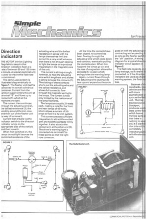
The early Lucas system is Ilustrated diagramatically in Figure 1. The flasher unit itself is ontained in a small cylindrical ..:ontainer. Current from the gnition supply enters the unit at :erminal "B" and flows up to ....ontacts (1), which at the moment are open.
The current then continues :hrough the actuating wire (2), :he ballast resistance (3), the Ninding around the iron core, and then out of the flasher unit Dy way of terminal L.
Current then travels via the ndicator switch to the direction ndicator lamps on the appropriate side of the vehicle and then to earth.
When first switched on, the amps do not light because the combined resistance of the actuating wire and the ballast resistance in series with the lamps themselves limit the current to a very small value so that there is not enough passing to light the lamps or to produce magnetism in the magnetic core of the unit.
The current is strong enough, however, to heat the actuating wire which lengthens and allows a spring to loose the contacts (1). The closing of these contacts shorts out the actuating wire and the ballast resistance, and allows full current to flow through the magnetic wiring to the lamps. The current is now only limited by the resistance of the lamp filaments.
The lamps are usually 21 watts each, making a total for the front and rear lamps of 42 watts, which allows a current of 3.5 amps to flow in a 12-volt system.
This current creates sufficient magnetism to attract the contact arm and hold the contacts firmly together. It also attracts the contact arm at the other end (5). The driver's warning light is connected via terminal P to these points so that the light now comes on. All the time the contacts have been closed, no current has been flowing through the actuating wire which cools down and contacts, eventually pulling the contacts open. When this happens the lamps go out and the loss of magnetism allows the contacts (5) to open which extinguishes the warning lamp.
Again, current flows through the actuating wire causing it to heat up and expand so the cycle goes on with the actuating wi contracting and expanding fc as long as the flasher switch i the "on" position. A wiring diagram for a typical directioi indicator circuit appears in Figure 2.
The flash rate depends on t lamp wattage, so if a trailer is connected, or if the direction indicators are used as a hazar .warning system, the flash rat less.
Because of till drawbacks, new vehicles are fittE with more sophisticated ut such as the Hell. unit. Thomas Electronics Ltd, Stockport, produces a solic state power flas which has no moving parts sc that there is nothing to wear out. It is claimec that this unit is completely interchangeabh with the stand& unit.