


Induction Hardening of Camshafts
Page 54
If you've noticed an error in this article please click here to report it so we can fix it.
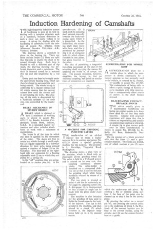
THE high-frequency induction system .1 of hardening is seen at its best in dealing with a complex structure such as a camshaft, because distortion in such • a piece can easily reduce it to, scrap. A set-up for dealing with the hardening of camshafts forms the subject of patent No. 656,866, from Allmanna Svenska Elektriska A.B., Vasteras, Sweden.
The drawing shows a camshaft in place on the heating jig. . There are three current looPs. (1); these are split like big-ends to enable the shaft to be passed through them. Each loop is shaped to suit a different part of th,,4 shaft, the drawing showing two different diameters and a cam-form. The shaft is indexed round . by a notched disc (2) and slid lengthwise by a rod (3)
Every part can thus be brought under the appropriate heating loop, which can then be closed to surround the part • being treated. The whole set-up is controlled by a master contact rod (4) which ensures that the current cannot flow until the correct coil is surrounding the work. The closing of the coils is determined by a hydraulic cylinder (5) On each one, also controlled by the master rod.
BRAKE MECHANISM OF STURDY DESIGN
BRAKE Which is claimed to ti have a minimum of working parts is shown in patent No. 657,117, by Bendix Aviation Corporation, South Bend, Indiana, U.S.A. It is intended mainly for tractors and other vehicles which have to work with a minimum of maintenance.
The brake is of the type in which One shoe is applied by the movement of the other. The shoes are free to rotate as a whole through a small angle, but are rigidly supported in a sideways direction by their webs being pressed against a number of ledges (1) on the back plate. The shoe-ends at the righthand side are connected by a floating adjustable strut (2) on to which they are pulled by a spring (3).
In the " off " position, they are springloaded on to anchor pins "(4). A flat spreader-cam (5) is used, and its actuating shaft extends inwardly towards the back-axle casing upon which it is journalled. As the shoes float, the actuating shaft must move with them, and this is permitted by journalling it in an elongated hole (6) which allows freedom in one plane, but gives location in the other.
The idea of permitting a tangential swivelling movement of the end of the actuating shaft carrying the means for applying the brake is, of course, not new. The present invention, however, simplifies the layout, in, , that no universal coupling, ball joints or similar types of connection are required.
A MACHINE FOR GRINDING INJECTOR VALVES
THE needle-valve of an oil-fuel injector has to make a highly accurate fit in its seating, and patent No. 657,129 shows a special grinding machine for the purpose. The patentee is L. Hartridge, Tingewick Road. Buck ingham.
The drawing shows a plan view of the machine, which is fitted with an electrically driven grinding wheel (1).
The valve is held in a V-shaped groove and is rotated on its own axis, thus ensuring automatic concentricity. The valve-holder is mounted on a compourtd sliderest (2) so that it can be fed past the grinding wheel while being manually rotated by means of a handle (3).
The top plate is pivoted at point 4 and can be accurately set for angle by adjusting screws (5). A dial-gauge (6) is incorporated so that ctanges in angle can be made with the piece under exact control.
The machine is also intended for the grinding of laps used to finish the female cone in the body of the injector. The lap is first ground in the machine, and then placed in a chuck (7) which revolves it, the injector body being held on to it by manual means. REFRIGERATION FOR MOBILE SHOP
6i REFRIGERATION plant for 4 mobile shop, in which the compressor is driven electrically by it battery separate to that normally used in the vehicle, is covered by G. French, of Cardiff,, in patent No. 657,369. The cotivenienee of' being. able to effect a quick change of battery so as to maintain with little interruption a comparatively silent source of power, . is the chief feature
a • strssed.
RE-SURFACING CONTACTBREAKER POINTS THE advice usually given in maintenance handbooks on facing up contact points is to keep them dead flat so that they meet squarely. Anyone with practical experience will know that this is -almost an impossibility, and usually an approximate seating is tolerated. A simple jig to give correct guidance in these circumstances is
shown in patent No. 657,168, by Li.
Kells, Air Base, Hobsonville, New Zealand.
The jig consists of a block provided with two flat faces (1) . and a partcircular exterior. TWo holes are drilled, one of which receives a pin (2) upon which the rocker-arm can pivot. By rubbing a file or oilstone along surface 3, the face of the point can be cleaned up so that it lies in the correct plane.
By pivoting the. rocker on a second pin (4), and pressing the contact point up to the underside of block 5, the fibre block of the contact breaker can be filed to the correct outline, using the circular part (6) on the contact-breaker base as a guide.