


Flexible Tanks for Road Vehicles
Page 36
If you've noticed an error in this article please click here to report it so we can fix it.
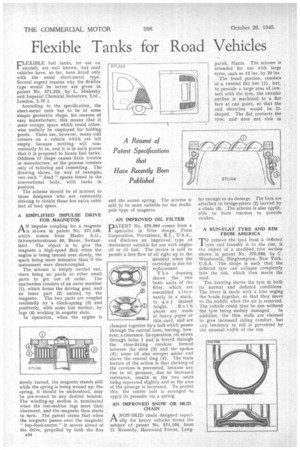
FLEXL13LE fuel tanks, for use on aircraft, are well known, but road vehicles have, so far, been fitted only with the usual sheet-metal type. Several cogent reasons why the flexible type would be better are given in patent No. 571,223, by L. Shakesby and Imperial Chemical Industries, Ltd., London, S.W.I.
According to the specification, the sheet-metal tank has to be of some simple geometric shape, for reasons of easy manufacture; this means that it must occupy space which could otherwise usefully be employed for holding goods. There are, however, many odd corners on a vehicle which are left empty because nothing will conveniently fit in, and it is in such places that it is proposed to locate fuel tanks. Oddness of shape causes little trouble in manufacture, as the process consists only of tailoring and cementing. The drawing shows, by way of example,two such " dead " spaces found in the conventional body, with tanks in position.
The scheme should he of interest to those designers who are constantly striving to obtain those few extra cubic feet of load space.
A SIMPLIFIED IMPULSE DRIVE FOR MAGNETOS
AN impulse coupling for a magneto is shown in patent No. 571,146, which comes from Hasler A.G., Schwartztorstrasse 50, Berne, Switzerland.. The object is to give the magneto a high-speed flick when the engine is being turned over slowly, the spark being more intensive than if the instrument were direct-coupled.
The scheme is simply carried out, there being no pawls or other small parts to get out of order. The mechanism consists of an outer member (1), which forms the driving gear, and an inner part (2) carried by the magneto. The two parts are coupled resiliently by a clock-spring (3) and positively, with some lost motion, by lugs (4) working in angular slots.
In operation, when the engine is slowly turned, the magneto stands sti 1 while the spring is being wound up; the spring, it should be understood, may be pre-wound to any desired tension. The winding-up motion is terminated when the lost-motion lugs meet their abutment, and -the magneto then starts to turn. The patent states that when the magneto passes over the magnetic " top-dead-centre " it moves ahead of the drive, propelled by both the flux a34 and the coned spring. The scheme is said to be more suitable for -the multipole type of magneto.
AN IMPROVED OIL FILTER
PATENT No. 570,960 comes from a specialist in filter design, Fram Corporation, Providence, R.I., U.S.A., and discloses an improved type of instrument suitable for use with engine oil or oil fuel. The device is said to perniit a free flow of nil right up to the moment when the cartridge is due for replacement.
T h e drawing shows the two basic units of the filter, which are assembled a Ite rnately in a stack, to a n y desired height. Both pieces are made of heavy paper or thin card, and are clamped together by a bolt which passes through the central bore, leaving, however, a clearance. In operation, oil enters through holes 1 and is forced through the close-fitting crevices formed between the slots (2) and the spokes (3); some oil also escapes under and above the central ring (4). The main feature of the action is that choking of the crevices is prevented, because any rise in oil pressure, due to increased resistance, results in the two units being separated slightly and so the area of the passage is increased. To permit this, the centre bolt is arranged to apply its pressike via a spring.
AN IMPROVED SNOW OR MUD CHAIN
ANON-SKID chain designed especially for heavy vehicles forms the subject of patent No. 571,104, from D. Kennedy, Harewood Forest, Long
far enough to do damage. The bars are attached to bridge-pieces (2) carried by a chain (3). , The scheme is also applicable to farm tractors to provide strakes.
A RUN-FLAT TYRE AND RIM FROM AMERICA
To remove the load from. a -deflated tyre and transfer it to the rim, is the object of a modified tyre section shown in patent No 570,988, by C. Woodworth, Binghampton, New York, U.S.A. The shape is such that the deflated tyre can collapse completely into the rim, which then meets the road.
The drawing shows the tyre in both its normal and deflated conditions. The cover is made with a bias urging the beads together, so that they move to the middle when the air is removed. The vehicle could thus be run without the tyre being unduly damaged. In addition, the thin walls are claimed to give increased riding comfort, but any. tendency to roll is prevented by the unusual width of the rim.