


A New Commer Combustion Chamber
Page 62
If you've noticed an error in this article please click here to report it so we can fix it.
A Resume' of Recently Published Patent Specifications
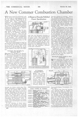
THE latest patent in connection with the design of combustion chambers for oil engines, No. 416,450, is by Commer Cars, Ltd., Luton, and H. 0. Farmer, M.C., B.Sc., A.Tvf.I.Mech.E., A.M.I.A.E., of Coneygarth, Church Stretton. The objects of the invention are twofold, i.e., to provide improvements in the location of a detachable combustion chamber, and to improve combustion characteristics.
Referring to the drawing, the location device consists of an eccentric boss (4) on an otherwise cylindrical combustion chamber. This boss fits into a corresponding bore in the cylinder head, and prevents misalignment of the passages. The chamber itself consists of two portions (2 and 3) held together by a clamping strap on the outside of the head.
The second improvement is based on the beating of the chamber by placing it in the path of the exhaust gases flowing from the passage (5), A deflector (1) is used to adjust the degree of heat applied to the top of the chamber.
Automatic Gear-changing by Hydraulic Means.
pTENT No. 415,395, by II. Russell, 152, Cross Road, Coventry, describes a contrivance intended to function automatically for gear-changing purposes. The system is hydraulically worked, and is to be applied to a gearbox in which the selector mechanism is controlled by cylinders and pistons.
The drawing shows the control me.chanism, comprising a selector (10) made in the form of a hollow sliding cylinder. A stepped piston (2) is disposed inside, and oil is supplied
-through the hollow centre piece 0(1). 'When _oil-pressure is applied through this pipe, the cylinder (10) is moved to the right, and comes to rest, in a position depending on the flow 'of oil, the only escape being the clearance between the stepped piston and the cylinder wall.. Attached to the lower side of the cylinder is a cam-track (9) controlling the individual valves (3 to 8), which admit pressure to reverse, brakes, three forward gears and clutch respectively.
As the selection of these valves depends on the position of the sliding cylinder (10), and this in turn, depends upon the flow of oil, it is surprising to
B48 read that the inventor's intention is that the oil flow shall be proportional to engine speed. This means that a certain engine speed would engage a definite gear ratio, which would be far from sufficient control on the road. It is true that manual operation is suggested as an additional control, in which case the automatic principle would seem redundant.
An Automatic. Strangler Release.
THE evils arising from running an enginetoo long with the strangler valve closed are well known, but nevertheless it may often occur, owing to the need for partial enrichment during the first few minutes of running. Patent No. 4.15,068 describes an addition to a carburetter for the purpose of rendering the choke control automatic, not only at starting, but also during such time as the engine takes to warm up. The patentee is the Bendix Aviation Corporation, 105, West Adams Street, Chicago, U.S A.
In this arrangement, the strangler valve is normally at rest in the closed position, being opened, and kept open by the engine suction in collaboration with the exhaust manifold temperature. In the drawing, the strangler control (4) is attached to an arm (2) fixed to a spindle (i). Fixed also to the spindle is a lever (1) connected to toggles (3 and 7). As shown, these toggles are'in line, and thus the whole strangler mechanism is locked in the closed position. When the engine is started, intake suction pulls down a piston (9) which causes a small freely mounted nose-piece (5) to thrust the toggles out of line, and so open the strangler. .
Temperature control is exercised by a coiled bi-metallic strip situated adjacent to the exhaust system. The central spindle of this strip is connected to the pivot (6); this also adjusts the position of the toggles.
Allowing for Road Camber in Rear. axle Design.
wirm twin-tyred rear wheels there WV is a considerable tendency for the inner tyres to take an undue share of the load on a cambered road, and to overcome this trouble is the object of patent No. 416,531, by John I. Thornycroft and Co., Ltd., and Sir J. E. Thornycroft, K.B.E. both of
Thornycroft House, Westminster, London, SAY.
As will he seen from the drawing, each half-axle shaft is inclined at about 3° to the horizontal. The drive is conveyed from the propeller shaft .(4) through a bevel diffetential gear (3) Carrying pinion§ (2) meshing with gears (1). The drawing shows these gears on only one side, but they are, of course, used on both. On the shafts carrying the gear (1) are mounted worms (5) which mesh with worm' wheels carried by the halt-axle shafts.
The specification further describes an over-speed gear which can also be conveniently located-in the axle casing.