


TIPPING . GE/ NOVATIONS.
Page 42
Page 43
Page 44
If you've noticed an error in this article please click here to report it so we can fix it.
Where Tipping Bodies are Necessar What the Shol -way and One-way Tipping Gears. to the Fore.
EFFICIENCY in the handling of all classes of transport has never been more necessary than it is to-day. Few people realize how much the cost of transporting•an article is 'reflected in its price. Take, for instance, coal: this, at the.pit mouth, costs 33s, 3d., but the consumer has to pay over double this price ; certainly, some of the extra cost is made up by the expenses and profits of the middle man, but the bulk of it is due, to the cost of transporting the coal from the pit mouth to the consumer. As with coal, so it is with every article that has to be carried, -whether the distance over which it has to be transported is a matter of yards or miles. With rising rates, the dearth of -houses, and the cost and scarcity of coal, the necessity for efficiency applies even more,particularly to transport for municipalities, building contractors, and the coal tracte, than for others. With labour at a premium, one of the chief 'factors in reducing transport costs is the reduction of the amount of labour required to load and unlOad vehicms. As regards unloading, many Materials, such as those employed in building, refuse, coal, etc., readily lend themselves to being unloaded by tipping the bodies of the vehicles on which they are being Carried. In our issue dated December 2nd, 1919,. we went very fully into the various types of tipping_ gears employed at that time. The Commercial Vehicle Show which was recently held at Olympia has brought to the fore several new types which deserve special consideration. Until recently, efforts to improve tipping gear have been confined to improvements in the mechanisin for effecting the tip, but this is not all that is wanted. End-tipping bodies and side-tipping bodies each have their own good points, and in certain places one or the other only can be employed. Where space is confined, it may be found impossible to unload a vehicle which has an end-tipping body only, whereas one provided -with a side-tipping body could deposit its load without any difficulty. Many 'instances occur when the position is reversed and where the end-tipping body is the one for the job. Hence tile contractor or municipal authority has to exercise considerable care in the selection of a vehicle suitable for a. particular class of work. If, however, it were possible ft) corq,bine the advantages of the end-tipping body with those of the side-tipping, one vehicle could be utilized for unloading at any spot, and it is in the design of tipping gears which will tip a body to either side or endways, as desired, that this Show has brought out several commendable efforts.
Three different types were exhibited. The most elaborate of these three-way tipping gears was certainly that on the five ton Saurer tipping wagon, and this has the particular advantage that it can be entirely
Controlled from theseat. This gear is operated hydraulically by an oil pump driven, from the gearbox. The body is supported on four ball joints, each provided with a bayonet faste,ning, capable of being locked or unlocked by a quarter turn. The cups of these ball joints are carried by the body, whilst the balls are supported on the ch2Ssis by two special hollow cross-members. From the cab a single rod passes through each of these two cross-members, and this rod is provided with gears and cross-shafts communicating with the bayonet joints. In the cab is a single lever, working in a gate and connected to the operating rod. By moving this lever sideways, the rod is turned, and a backward movement of the lever into one ef three gates releases the bayonet joints at either side or the front, according to the direction in' .which it is desired to tip the body. Another lever; also situated in the cab, is then moved to operate the valve controlling the supply of oil to a. hydraulic ram. This f^am carries rack teeth which engage with a pinion carrying a very powerful lever shaped into the form of a bell-crank. At the front .end of this lever are universally jointed arms carrying a ball, which bears in a cup supported by the powerful underframe work of the body ; as the ram is pushed out the lever is lifted, consequently lifting the body, which naturally swivels on those ball joints, the bayonet fastenings of which are not released. At the
maximum point of tip, a release valve comes into operation. so that the tipping angle cannot be exceeded.
Another feature of this gear is that the sides of the body are automatically locked, whilst the body is at rest, and are automatically released at the sid to which the tipping is to be done. • Whilst the be • y is actually tipping it is impossible to move the 1 ver controlling the bayonet fastenings, so that accid nts cannot occur from this cause.
Our criticisms of this gear are that it appears ery expensive to manufacture, and there might, be s me difficulty in making the body return, so that the sails and sockets exactly coincide, if the vehicle wer so positioned that frame distortion occurs, also the a.ck and the pinion of the lifting lever appear to be u der enormous stresses.
A somewhat similar but less complicatedgear -a.s that shown on the 6 ton British-Berna tipping wa on. This gear, however, Is operated by a screw and nut with square threads. At the top of the gearbox are two constant mesh pinion, either of which can be locked to a shaft carrying the large phosphor-bronze nut by means of a double dog • clutch. It will be understood that by moving this dog clutch in one direction the body is lifted, and in the other lowered.
.-The. phosphor i
-bronze nut s supported in ball bearings. The screw is fastened to a crosshead somewhat' similar to that on a locomotive, and links connect this crosshead to the lower arm of a huge bell-crank lever; which is pivoted on to a stout chaantel-steel frame carrying the nut and. crosshead. At the other end of this bell-crank lever is a short, stout, universally jointed shaft pivoted to the centre of the steel frame supporting the body. When at rest, the.body is supported on four steel brackets, bolted to the frame side members, and rocked into position by stout nins. The brackets on the .body framing form the female portions of hinges, whilst those on the chassis can swivel in the other direction, thus making a type of universal joint.
To tip the body to either side or to the rear, the locking pins at the opposite side or end are withdrawn, and the sliding dog put into mesh with dog teeth on one of the Constant-mesh pinions. The bell crank then rises rapidly and tips the body. The angle of tip in each direction is quite surprising ; to the rear it is 55 degrees and to the side 35 degrees. To prevent any danger of overtipping or jamming of the worm and screw, when the body lifts to its maximum height it tightens.a chain which, through the medium of levers and rods, pulls the dog clutch out of mesh with the constant-mesh pinion. A similar action occurs when the body is lowered, but, in this case, the body, as it coolies to rest, depresses a lever. In this type of gear the stresses on the operating mechanism do not appear to be nearly so great as those on the gear which we described previously, although it does not, possess the advantage of being capable of being operated entirely from the driver's seat.
Another neat device utilized with this gear is a spring stop, which is automatically dropped over each rear spring as the body tips, and thus prevents the rear springs from being strained by the extra. load thrown on them when a loaded body is tipped. Also, when the body is at rest, the four locking pins take no load. An additional advantage is that the whole of the operating mechanism is totally enclosed and runs in oil.
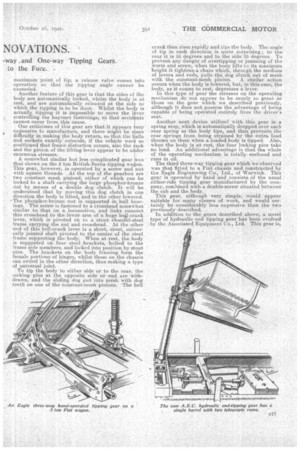
The third three-way tipping gear which we 'observed was that fitted to a Fiat chassis and constructed by the Eagle Engineering Co., Ltd., .of Warwick. This gear is operated by hand and consists of the usual* .either-side tipping gear manufactured by the company,,combined.with a double-screw situated between the cab and the body. This gear, although very simple, would appear suitable for many classes of work, and would certainly be considerably less expensive than the two previously described. In addition to the gears described above, a novel type 'of hydraulic end tipping gear has been evolved by the .Associated. Equipment Co., Ltd. This gear is, in certain respects, similar to the well-known Wood hydraulic, and it is situated in the same place, between the cab and the body. The Wood gear, however, owing to its pulley and wire ropes, takes up a considerable amount of room, whereas the A.E.C. gear is a slender steel barrel provided with two rams, one of which telescopes mtu the other. The upper ram carries a T piececonnected to brackets on the body by two steel strips.
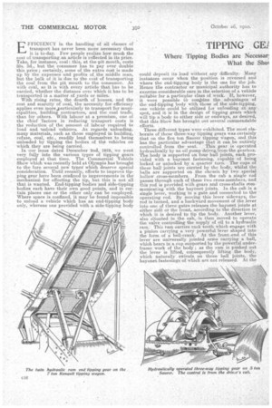
When in operation the body is lifted to a certain height by the large ram, and is then tipped to a greater angle by the small ram. In this gear the hydraulic pump, which is of -the doubleplunger type, is driven by a pinion carried in the top of the gearbox. This gear will tip to an angle of 40 degrees in 30 seconds, and, after tipping, the body drops back between stout steel guides bolted to the frame side members. The price of the outfit, including a steel tipping body, is 2225. One very substantial twin-ram hydraulic and tipping gear was observed on a 7 ton Renault tipping wagon ; in this gear the rams are positioned well to the rear of the chassis, and, to prevent the front portion of the body from swaying, a stout angle-iron stay is positioned between the chassis and body ; the end of this stay is free to slide longitudinally on a bar attached to the latter.
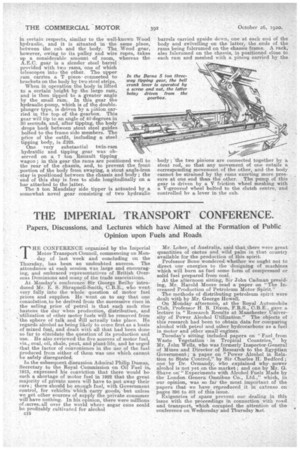
The 5 ton Maudslay side tipper is actuated by .a somewhat novel gear consisting -of two hydraulic
barrels earriecl upside down, one at each end Of the body and swivelling on the latter, the ends of the rams being falerumed on the chassis frame. A rack, also fulcrumed on the chassis, -is positioned close to each ram and meshed with a pinion carried by the body; the two pinions are connected together by a stout rod, so that any movement of one entails a corresponding movement of the other, and the body cannot be strained by the rams exerting more pressure at one end than the other. The pump of this gear is driven by a V friction wheel meshing with a V-grooved wheel bolted to the clutch centre, and controlled bv a lever in the cab.