


A Novel Two-stroke Engine
Page 64
If you've noticed an error in this article please click here to report it so we can fix it.
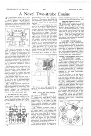
N unorthodox design for a twostroke engine comes in patent No. 717,168 (G. Manley, The Old Rectory, Henley in Arden, Warwickshire). Although the patent deals mainly with the exhaust system, the engine possesses other interesting features.
The piston is extended to form a lower cylindrical portion (1) which slides through a seal and acts as an air pump. It draws in atmospheric air from a port '(not shown) fitted with a one-way valve and compresses it on the downstroke. The compressed air is discharged, immediately after exhaust, into the cylinder via port 2. At a later point in the stroke, atmospheric air from a belt (3) enters the cylinder via another port (4).
The exhaust system, upon which the patent is based, consists of a ring of piston-controlled ports leading into ducts (5). These are also curved in a direction round the cylinder. axis and finally discharge via annular gaps (6) into the main outlet (7).
The exhaust gases are thus given a forceful swirl in the annular chamber (8) and this is said to exert an evacuating action on the cylinder space when the ports are open.
The engine described presumably employs petrol injection, as both injector and sparking plug are mentioned. The exhaust scheme is, however, said to be equally suitable for compressionignition engines, and may even be adapted to suit a four-stroke unit.
A SIX-SPEED BUS GEARBOX THE latest German practice in the design of passenger vehicle gearboxes is disclosed in patent No. 717,181. by Zahnradfabrik Friedrichshafen A.G.
Friedrichshafen on the Bodensee, Germany. The gearbox described will give six forward speeds and yet is said to be no longer than a conventional gearbox.
The method of engaging the main ratios is by means of friction clutches, one to each speed. The clutch is mounted upon the slower-moving shaft, so that when in use it has only a small speed variation to bridge. The ratio between successive speeds is a constant.
The input shaft (1) and the output shaft (2) are co-axial and are locked together by the two clutches, 3 and 4, to give top gear. As there are two clutches in this main shaft, the layout almost amounts to two normal gearboxes in series, a method which will square the number of ratios available in one box.
One dog-clutch (5) is used; this chooses first or second speed, whilst the friction clutches deal with the others. Reverie is provided by meshing the three special gears shown at 6, 7 and 8.
The patent gives full details of the duties of the various gearwheels in all the ratios.
THE LATEST IN DISC-BRAKE DESIGN
DATENT NO. 717,101, comes from
Girling, Ltd., Kings Road, Tyseley, Birmingham. It discloses the latest improvements in the design of ,disc. brakes. There is no great departure from standard principles, the patent being based on the particular construction employed.
The pressure cylinders, three in number, arc machined in a steel forging of kidney shape. The cylinders are fitted with liners (1) having shoulders on their outer ends; these fit in counterbores in the forging and have a sealing ring (2) applied. When the outer endcovers are bolted on, they compress these seals and so close the joint. The pistons have a common connection to the supply of hydraulic fluid.
The whole assembly is bolted to a torque-resistant flange (3) which is pressed from heavy-gauge steel. This is bolted to a stationary part of the axle.
CLUTCH THRUST-RINGS
AMORE durable material for clutch thrust-rings is shown in patent No. 714,946, by C.D. Patents Ltd., 19 Berkeley Street, London, W.1. It consists of carbon impregnated with a hard heat-resisting thermo-setting resin,*plus boric acid or one of its salts. A fatty acid or a glyceride thereof may also be added. Tests have shown that only 0.01 in, wore off after 20,000 clutch movements. The patent gives details of the manufacturing process.
VARIABLE VALVE-TIMING I N patent No. 716,997, Daimler-Benz A.G. disclose a design for a valveoperating gear that can be advanced or retarded so as to give optimum valve events for all conditions of speed and load, The specification is descriptive only and contains no drawings. Control of the adjustment is by a combination of engine speed and intake suction.
A SIMPLE AUTOMATIC ADVANCE FOR INJECTION PUMPS
AN automatic-advance coupling for driving the injection pump of an engine comes in patent No, 716,072, from Klockner-Humboldt-Deutz A.G., Cologne-Deutz, Germany. Not only is the mechanism simple and sturdy, but its action approximates to a linear law instead of the embarrassing square-law response of the usual centrifugally operated devices.
In the drawing, 1 is the driving member and 2 the driven part. Relative movement between the two is permitted against the force of tangential springs (3). The movement is produced by four wedge-shaped centrifugal weights (4) which, by moving outwards, spread the gaps between the driving abutments (5) and the driven ones (6).
If all the weights moved together, the outward force would vary as the square of the speed. But this is not so; the four springs vary in strength, so that the weights move in succession. Although this action does not give a true linear response, it gives four spaced parabolas, which form a practicable approximation.