


Monobloc Casting for a Flat Four
Page 76
If you've noticed an error in this article please click here to report it so we can fix it.
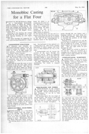
.PATENT No. 863,246 discloses a design I for a four-cylinder horizontally opposed engine in which the cylinder block is formed as a single casting. The block also includes the housing for the upper halves of the main bearings. (Ford Motor Co., Ltd., 88 Regent Street, London, W.I.)
Referring to the drawing, the casting comprises the four cylinders (1), a camshaft bearing housing (2) and tappet guides (3).
The main bearings are supported by webs, each bearing being held in a slipper LIGHTWEIGHT EXHAUSTER
AN exhauster unit intended for vacuum-operated brakes forms the subject of patent No. 862,662. Its chief points are said to be light weight and cool running. (Clayton Dewandre Co., Ltd., Titanic Works, Lincoln.)
Referring to the drawing, a light-alloy body is die-cast around a cast-iron liner (1). The eccentric rotor is also die-cast in aluminium alloy and carries sliding fibre vanes (2). Holes (3) are provided for lightness.
Cam rings (4) cause the vanes to move outwards so that the outer edges remain in contact with the liner. The rings are located in end plates which are springloaded against the vanes to form a seal.
The driving spindle projects at both ends and is fitted with scaling glands. The suction port is shown at (5) and the exhaust at (6). Positive lubrication is provided via an oil filter (7), the suction ensuring adequate distribution. References are made to an earlier patent numbered 752,064.
DISCONNECTIBLE FOUR-WHEEL DRIVE IVIODIFICATIONS to a four-wheelIVI drive vehicle form the subject of patent No. 862,708. The invention consists of a means of freeing the front wheels from their half-shafts when not required to drive. (Ribblesdale Motors' Ltd., King's Mill Lane, Settle, Yorks.) The drawing shows a section of a front RA
block (4) which is an interference fit in the casting. The block is located axially by a tongue-andgroove fitting. An upper member (5), also an interference fit on its edges, forms an abutment for the boring block and acts also as a tension strut across the top of the casting.
The connecting-rod joint (6) is inclined to the axis of the connecting-rod to facilitate access to the big-end bolts.
hub. The half-shaft (I) has splined to it a sliding sleeve (2). This carries a double dog-clutch (3) which engages with teeth (4 or 5) when displaced one way or the other.
A spring-loaded ball (6) locates the position of the sleeve through two grooves (7 and 8). These are connected by a helical groove (9) so that when the half-shaft begins to rotate following the engagement of four-wheel drive, the dogclutch is engaged and a drive established.
In other applications shown in the specification, the clutch is engaged manually.
SEMI-TRAILER FOR TIMBER
ASEMI-TRA1LER for the transport of rough timber is shown in patent No. 862,990. (Societe d'Importation de Bois Exotiques, 21 rue de la Ville l'Eveque, Paris 8.)
The drawing shows the rear bogie of the semi-trailer. The tractor is fitted with S.A.E. fifth-wheel coupling to receive the front end of a tubular member (1) This tube is straight throughout. 1 passes through the rear bolster and a clamping member (2), both being part of the bogie assembly_ When the clamp is loosened the position of the bogie can be adjusted.
• Braking is by compressed air and the hose for this is wound on a spool (3) so that its length can be varied. A running gland connects the spool with the brake pipe. The rear light cables (4) pass through the tube.
Spare wheels are carried as shown at (5) and (6). They are mounted on a swinging arm to facilitate removal. Their weight is said to help stabilize the trailer when running unladen.
CONSTANT-LEVEL SUSPENSION A LEVELLING valve for an air-sus pension system is shown in patent
No. 862,896. (Clayton Dewandre Co., Ltd., Titanic Works, Lincoln.) The drawing is a section through the valve. The compressed-air supply is fed to the port (I) while the other port (2) leads to the air spring. The lever (3) is connected to the axle and as it moves an eccentric pin (4) is turned.
Journalled on this pin is a rocking lever (5), one end of which engages with an inlet valve (6) and an exhaust valve (7) he right-hand end being held in the spring box (8). The two valves open in opposite directions and when the lever is rocked one or the other is opened depending on the direction of movement.
In operation, gradual changes of load are not resisted by a hydraulic damper (9) and the inlet or exhaust is opened to adjust the pressure in the air spring. But violent changes, such as road shocks, cannot move the damper, and in these circumstances the lever pivots about the pin (10) and the movement is accommodated by the spring box. The spring box also keeps the lever, when at rest, in the mid-position in which both valves are closed.