


Springing System for
Page 56
If you've noticed an error in this article please click here to report it so we can fix it.
Multi-axle Vehicles PATENT No. 503,441 comes from Automobiles lndustriels Latil, 8, Quai Gallieni, Suresnes, France, and refers to vehicles of the multi-axle type. Such vehicles are usually fitted with compensated suspension, so that all the wheels share the load on uneven ground. However, should the machine have to traverse a trench or otheeconsiderable depression, one pair of wheels may sink so deeply as to "ditch "the vehicle. The present patent deals with a means for temporarily immobilizing the flexibility of the suspension, so that, in such circumstances, one axle may be carried over the trench.
Referring to the accompanying draweig, it will be seen that the springs are, at their outer ends, shackled to frame pins (2 and 4), whilst the inner ends are coupled to a rocking beam (3). In normal use, the rocking beam allows one wheel to rise as the other falls, thus ensuring equal distribution of the load. In the circumstances outlined above, however, the rocking beam can be locked in the mid-position by a catch (1) engaging in a notched quadrant ; by this means wheel movement is limited to the flexibility of the springs alone.
Liquid-cooled Injection Nozzle.
AN injector, through which liquid is circulated for cooling purposes, is shown in patent No. 503,432, by G. Green, and Bryce, Ltd., Kelvin Works, Hackbridge, Surrey. In this design,
cooling liquid arrives via duct 5 and passes through segment spaces (4) formed between flats on the body and the outer sleeve (3). Reaching annular space 2, the fluid passes around the body and leaves via a second segmental space (1), finally passing out of another duct similar to 5.
A38
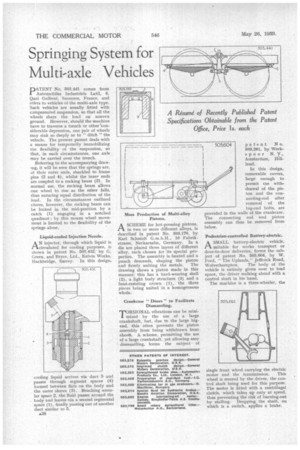
ASCHEME for hot-pressing pistons, in two or more different alloys, is described in patent No. 503,170, by Karl Schmidt G.m.b.H., 10 Fahrik strasse, Neckarsulm, Germany. In a die are placed three layers of different alloy, each chosen for its special properties. The assembly is heated and a punch descends, shaping the piston
and firmly uniting the metals. The drawing shows a piston made in this manner; this has a hard-wearing shell (2), a light body structure (3) and a heat-resisting crown (1), the three pieces being united in a homogeneous whole.
Crankcase " Doors " to Facilitate Dismantling.
TORSIONAL vibrations can be mini' mized by the use of a large crankshaft, but, due to the large bigend, this often prevents the piston assembly from being withdrawn from abovt. A scheme, permitting the use of a large crankshaft, yet allowing easy dismantling, forms the subject of
patent No. 503,261. by Werkspoor N.V., II‘ Amsterdam, 01land.
In this design, removable covers, large enough to permit the withdrawal of the piston and the connecting-rod after removal of the big-end bolts, are provided in the walls of the crankcase. The connecting rod and piston assembly can thus be removed from below.
Pedestrian-controlled Battery-electric.
ASMALL battery-electric vehicle, suitable for works transport or door-to-door deliveries, forms the subject of patent No. 503,304, by W. Ford, "The Uplands," Jeffcock Road,
Wolverhampton. The body of the vehicle is entirely given over to load space, the driver walking ahead with a control shaft in his hand.
The machine is a three-wheeler, the single front wheel carrying the electric motor and the transmission. This wheel is steered by the driver, the control shaft being used for this purpose. The motor is fitted with a centrifugal clutch, which takes up only at speed, thus preventing the risk of burning-out by stalling. Dropping the shaft, on which is a switch, applies a brake.