


Patents Completed.
Page 20
If you've noticed an error in this article please click here to report it so we can fix it.
Complete specifications of the following patents will be sent to any address in the United Kingdom upon receipt of eightpence per copy at the Sales Branch, Patent Office, Holborn, W.C.
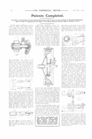
MOTOR ROAD VEMCLE.—Daimler Motor Co. (1904), Ltd., and LimeIhster. --No. 9,259, dated 19th April, 19C9.This invention relates to heavy motor vehicles such as motor omnibuses, vans. etc., and has fur its object to provide an improved construction and disposition of the frame and power-producing and &iv ing mechanisms. The frame Of the vehicle is made of steel plate and is formed with a channel that runs lengthwise of the vehicle and having flanges at either side. The channel portion of the frame may form the floor of the vehicle, and the flanges, in the case of a motor omnibus, may support the seats. The frame is stiffened laterally by a number of angle bars, and a fuel faith Is disposed in the channel towards the front of the vehicle. Two separate power-developing and driving units ale provided, one directly beneath each flange of the frame. Each driving unit may comprise a petrol motor driving an electric motor, which latter drives one of the road wheels through the medium of a cardan shaft and a worm gear. A storage battery is provided to take the surplus current when the power required to drive the vehicle is below the normal, and this storage battery is arranged to supply additional current in order to assist the motor when an unusual de. mand for power is required, as when ascending hills, for example. Each of
the rear wheels, as before stated, is separately driven and is carried by a sleeve, which is mounted in a bracket that supports the springs and also the rear axle. TRACTOR WHEELS. — Brey.—No. 26,368 of 1909, dated under Convention November 13th, 1908.—This wheel is especially designed for tractors employed in hauling heavy loads over F...At soil. In the illustration, a steerable wheel is shown which is also driven from the source of power through suitable gearing. The wheel comprises a hub having a conical flange, to which are bolted the spokes of the wheel on one aide and a curved annular member on the other side. The spokes and the annular member carry hoops or rings, and, extending laterally across the face of these rings, are slats or bars, suitably rpaced apart,
so as to form spaces through' which the mud or soft soil is allowed to pass and travel to the side of the wheel. A second rim or band surrounds the slats or cross-bars and is disposed midway of the tread of the wheel. It will be seen that, owing to a free passage's being provided for the soft soil between the slats, clogging is prevented, and, consequently, the wheel obtains a better grip. The drive is effected through the medium of a sprocket-wheel, which drives the wheel through bevel gearing.
ROAD LOCOMOTIVES.—Fowler and Tner.—Nn. 12.020, dated 21st May, 1909. —This invention relates to the connection between the axle and the body of a road locomotive. The bearing bushes of the axle are carried in a sleeve, which latter has knuckle lugs or projections
that enter a recess formed in the circular flange of the horn block. These lugs or projections form a bearing centre about which the sleeve is permitted to osci)late. At the side of the sleeve, dia
metrically opposite to the projections. a hearing surface is provided which contacts with a similar bearing surface provided on the flange of the horn blocks. The sleeve is provided with hooks that accommodate the buckles for the springs. which latter support the horn blocks_ Iii this way the sleeve, together with the axle bearings, is permitted a limitad oscillatory movement about the axle of the knuckle lugs or projections in the sleeve member.
MPS.—LEunplotigh and Others.— No. 16.529. dated 15th July, 1909.--This invention relates tu a device for varying the stroke of pumps. The driving shaft of the pump carries a plate having concave and convex portions, both of which have the same centre. Fitting these concave and convex portions of the plate, is a second plate which is permitted to slide or to oscillate relatively to the first plate. This second plate carries the strap of the connecting rod that operates the pump plunger. A lever is pivoted to the frame of the pump and carries a similarly-shaped member, which is connected to the second plate in such a manner that, by moving the lever up or down, the second or driving plate is moved out. of concen
tricity with the driving shaft. The degree of eccentricity can be varied by moving the lever up or down, and thus the stroke of the plunger may also be varied. The movements of the lever are preferably controlled by the pressure of the pump so that a constant predetermined pressure can he maintained. This mechanism is applicable for use with ratchet motions.